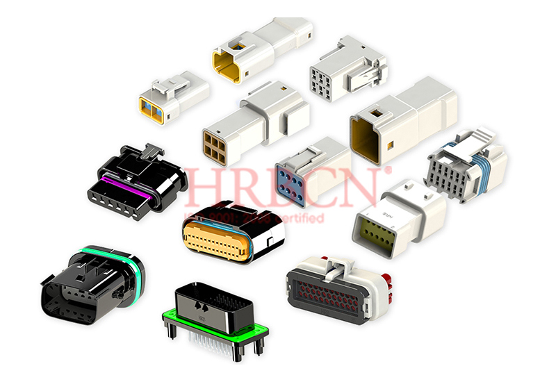
Imagine your prototype fails in the field because a melted connector causes costly downtime. Safety recalls, like airbag failures in over 300,000 vehicles, show the stakes. How do you pick the right electrical connector from thousands of choices? This guide gives a clear, step-by-step plan based on electrical, mechanical, and environmental needs. It turns connector selection from a guessing game into a precise engineering choice, saving you time, money, and stress. A wrong connector type can lead to recalls, including fire risks from bad wiring. For many uses, circular electrical connectors offer strong performance. Picking the right circular connector ensures reliability in tough conditions. This organized method helps you choose electrical connectors for different uses, boosting performance.
Key Takeaways
For long-term reliability, run connectors at 70-80% of their rated current.
Match IP ratings to your environment to stop moisture from causing failures.
Use crimp terminals when there is a lot of shaking or movement. Use solder when the part stays still and faces little stress.
Check that the maker has UL, VDE, and ISO certifications to confirm their quality.
Assess Electrical Specifications for Your Electrical Connector
Before you check physical fit or environmental resistance, you must first make sure the electrical connector can handle the power and signals your application needs. This step protects your design from overheating, signal corruption, and early failure. You need to look at two key factors: current and voltage ratings, plus signal integrity needs.
Current and Voltage Ratings
Every electrical connector has a current rating and an operating voltage rating. These numbers show the maximum safe electrical load under set conditions. You must pick a connector type that goes beyond your actual needs, not one that just meets them. For high-power uses, HRB's wire-to-wire connectors offer larger pitch options, which fit thicker terminals and release heat better. Smaller pitches work for signal-level connections where current demands stay low.
Industry practice suggests running at 70–80% of the rated current for long-term reliability. This derating rule accounts for real-world conditions: higher ambient temperatures, limited airflow, and many energized connectors in a tight space. No strict standard requires this margin, but experienced engineers treat it as a must-have safety buffer. You should use the same approach when sizing your connectors.
Going past current ratings causes a chain of problems. Joule heating, calculated as power equals current squared times resistance (P = I²R), raises temperatures quickly. Contact resistance grows over time due to oxidation and stress relaxation, which makes heat worse. The results include insulation breakdown, equipment burnout, faster aging, and safety risks. Consider this example: at 200A, an increase of 0.1 mΩ in contact resistance adds 4 watts of heat at one contact point. Localized temperatures can go above 120°C, far past safe operating limits. Poor contact resistance is thought to cause 30% of battery failures, leading to overheating and lower efficiency.
Run at 70–80% of rated current for long-term reliability
Consider ambient temperature, airflow, and connector density
Watch contact resistance as it grows with oxidation and stress relaxation
Check designs with environmental testing like Double 85 (85°C/85% RH for 1008 hours)
Signal Integrity and Data Needs
Modern applications increasingly send data along with power. Your electrical connectors must keep signal quality without adding noise or distortion. Signal loss happens through several ways: signal reflections from impedance mismatch, attenuation from signal loss, and crosstalk or electromagnetic interference from nearby conductors.
Poorly designed connectors can cause impedance mismatches, crosstalk, and signal reflections, all of which lead to signal loss. Weak shielding or bad grounding can result in electromagnetic interference (EMI), further hurting signal integrity.
You can reduce these issues through careful design choices. Keep signal lines short and return paths wide to limit impedance breaks at connectors. Match propagation delays of related signal and clock lines to prevent timing errors. Pick low-loss PCB materials and control trace shape to reduce signal loss. Increase space between nearby traces, such as using the 3W rule, to cut crosstalk. Design a power distribution network with low impedance to reduce power and ground noise.
For mixed power and signals uses, you may need separate connector types within the same system. HRB's wire-to-wire connectors support both functions, but you must match the pitch and terminal design to each signal's needs. Circular electrical connectors often work well in these cases because their design provides steady impedance control and shielding options. The right circular connector type ensures reliable performance across both areas.
Your choice of electrical connectors directly affects system reliability. By checking current rating, operating voltage, and signal integrity together, you build a base for strong performance. This organized approach prevents costly redesigns and field failures. Next, you will look at mechanical fit to ensure your connectors physically fit with your design.
Evaluate Mechanical Fit for Electrical Connectors
Once you make sure the electrical specs work, you must check that the connector fits your design physically. The mechanical fit decides if the connection stays tight during assembly, use, and repair. You need to look at three things: size, how it mounts, and how it locks.
Size, Mounting, and Locking
The size of your connector must match the space you have. You can't skip this step. HRB's wire-to-board connectors show how design changes to fit different PCB layouts. You can pick right-angle headers for low-profile builds or vertical headers for straight connections. Single-row setups work for simple circuits, while dual-row options handle more pins in the same area.
Your choice of mounting style affects how stable the connector is. Through-hole (THT) parts create a strong bond because leads go through the board and anchor firmly. This makes THT great for cars, planes, or military gear that faces physical stress. Surface mount (SMT) parts are smaller and let you pack more circuits, but they break more easily under stress or twisting. For handheld devices and high-speed signals, SMT works well. For connectors that get plugged in many times, THT gives better reliability.
Locking mechanisms keep the connector from coming loose. A secure latch or friction lock holds the connector in place even with shaking. HRB's wire-to-board connectors have strong locking parts that handle stress during use. You should always check that the lock matches how much shaking your application will have.
Industry standards tell you how to test mechanical reliability. IEC 60512 gives standard ways to measure insertion force, pull-out force, and how many times you can plug it in. USCAR-2 lists mechanical performance needs for high-reliability uses. These tests help you guess how long the connector will last and find failure risks before you use it.
Termination Styles: Crimp, Solder, and IDC
Your termination method decides how the wire connects to the terminal. Each style has its own benefits and downsides.
Crimping makes a cold-weld joint by squeezing the terminal barrel around the wire. Done right, crimps give great mechanical strength and electrical flow. According to USCAR-21 testing, crimped connections last 15+ years in tough car environments. The key is using the right crimp tool and die for your terminal size. You must match the wire size to the terminal barrel diameter exactly.
Soldering joins the wire to the terminal using melted metal. While solder makes a solid electrical connection, it has a big weakness. Solder hardens into a crystal structure that is not very flexible. Under shaking or bending, stress builds where hard solder meets flexible stranded wire. This stress starts cracks that grow with each shake. Soldered connections usually weaken after 5-7 years in harsh places, while proper crimped joints last decades.
Insulation Displacement Connectors (IDC) offer a third option. IDC technology removes the need to strip wire. A sharp fork in the terminal cuts through the insulation and touches the wire inside. This saves installation time and lowers error risk. HRB's IDC connectors work with various wire sizes and come in multiple pitch options. They work well for ribbon cables and mass-termination jobs.
Your choice of termination style affects long-term performance. For uses with shaking or temperature changes, crimping gives better reliability. For quick assembly and tight spaces, IDC saves time. Soldering works best in low-stress places where flexibility is not needed.
The mechanical fit of your electrical connectors directly affects system reliability. By checking size, mounting, locking, and termination together, you make sure physical fit for all uses. This step-by-step method prevents field failures and costly redesigns. Next, you will look at environmental resilience to make sure your connectors survive harsh conditions.
Consider Environmental Resilience
Your connector's operating environment determines its lifespan more than any other factor. Moisture, temperature swings, and vibration attack connections silently, degrading materials until failure occurs. According to industry research, moisture ingress is a leading cause of connector failures in automotive applications. You must evaluate your environment honestly before finalizing your choice.
Temperature and Moisture Protection
Temperature extremes stress connector materials in opposing ways. Heat accelerates oxidation on contact surfaces, increasing resistance and generating more heat. Cold makes housings brittle and seals less flexible. Moisture compounds these problems by enabling corrosion and electrochemical migration between adjacent contacts.
IP ratings provide your first line of defense against liquids and dust. These two-digit codes tell you exactly what your connector can withstand. For outdoor sensors and renewable energy arrays, connectors with temporary immersion protection are suitable. Marine equipment and wastewater treatment demand connectors with continuous submersion capability. Automotive wiring and food processing lines require protection against high-pressure washdown. Over-specifying to a higher protection level for simple outdoor installations adds cost without functional value, while under-specifying for washdown environments leads to rapid seal failure.
HRB designs connectors for specific industry challenges. Agricultural machinery connectors withstand rainstorm conditions, protecting critical circuits during prolonged field exposure. Industrial automation connectors deliver absolute reliability in humid factory environments where condensation forms regularly. These specialized designs incorporate sealed housings and corrosion-resistant materials that maintain performance under constant moisture stress.
Testing validates your environmental choices. The 85/85 test (85°C with 85% relative humidity for 1008 hours) reveals corrosion, insulation degradation, and electrochemical migration. Passing these tests gives you confidence that your electrical connectors will survive years of real-world exposure.
Vibration and Mechanical Stress
Vibration causes fretting corrosion, a leading failure mode where micro-motion between contact surfaces wears away protective plating. This mechanism accounts for high contact resistance in approximately 45% of all harness failures. Under constant current, this resistance generates abnormal heat, potentially melting connectors or causing fires.
Standard vibration testing includes simple harmonic motion at specified frequencies and amplitudes, swept for a duration in each of three perpendicular directions. Failure symptoms include intermittent contacts, chafed wiring, and loosened fasteners. Standard vibration testing covers sinusoidal vibration for rotating machinery environments and random vibration from transportation and vehicle use.
Mitigation starts with proper terminal selection. Gold or tin plating resists fretting corrosion effectively. Automated crimping with real-time force monitoring ensures consistent termination quality. Adequate harness support and tie-down points reduce vibration transmission to connector interfaces. High-retention force terminals maintain contact pressure even under continuous mechanical stress.
For demanding applications, circular connectors offer inherent advantages. Their symmetrical design distributes mechanical stress evenly across the connector body, reducing localized fatigue points. This structural resilience makes circular options particularly suitable for industrial automation and transportation applications where vibration persists continuously. HRB's industrial automation connectors maintain precise accuracy through millions of operational cycles, even in humid, vibrating environments.
Review Materials, Compliance, and Sourcing
You have checked electrical specs, mechanical fit, and environmental resilience. Now you must verify materials, certifications, and your supplier's reliability. These final checks protect your design from safety failures, legal issues, and supply chain disruptions.
Material Selection and Plating
Contact materials determine how well your connector transmits current and resists wear. Conductivity affects transmission efficiency directly. Yield strength indicates when plastic deformation begins, which matters for contact retention. Thermal conductivity governs heat dissipation. Corrosion resistance protects against environmental degradation. Elastic modulus reflects stiffness and mechanical stability. Hardness affects wear resistance. Formability determines how easily manufacturers shape the contact.
Material Property | Functional Relevance |
|---|
Conductivity | Affects current transmission efficiency |
Yield strength | Critical for contact retention |
Thermal conductivity | Governs heat dissipation |
Corrosion resistance | Protects against environmental degradation |
Hardness | Affects wear and deformation resistance |
Plating choice significantly impacts long-term performance. Gold plating offers excellent corrosion resistance and supports a high number of mating cycles. This makes gold ideal for harsh environments with high vibration. Tin plating costs less but forms oxides quickly and supports fewer mating cycles. Tin also suffers from fretting corrosion and whisker growth, which can cause short circuits. For demanding applications, gold's higher initial cost pays off through reliability and longevity. For static, benign environments, tin works fine.
Certifications and Manufacturer Reliability
Certifications verify that your connectors meet recognized safety and quality standards. UL approval comes from Underwriters Laboratories, an independent safety science organization. VDE certification ensures compliance with German and international standards for safety, quality, and reliability. ISO 9001 confirms the manufacturer's quality management system meets international requirements. HRB holds relevant certifications, demonstrating commitment to compliance across global markets.
Non-compliance carries severe consequences. European markets require CE and RoHS compliance. Ignoring these standards can invite fines reaching tens of thousands of Euros. Customs may destroy non-compliant shipments. Importers, distributors, and retailers share liability if they fail to verify compliance. These risks can cascade into broken contracts with major brands.
Manufacturer reliability depends on in-house capabilities. Precision stamping determines dimensional accuracy and electrical performance of contacts. Injection molding ensures mechanical alignment and insulation. Final assembly requires precise pin insertion. Full-process quality control ensures consistency across all stages. HRB operates as a full-service manufacturer with in-house mold making and stamping. This vertical integration ensures high quality control and reliable supply. You avoid delays and quality variations that come with outsourcing critical production steps.
Choosing a manufacturer with these capabilities simplifies your sourcing. You get consistent quality, regulatory compliance, and dependable delivery. This final validation completes your connector selection process.
Selecting the right electrical connector is a systematic process of elimination. You start with electrical specifications to ensure safety. Then you evaluate mechanical fit for physical compatibility. Finally, you validate environmental resilience and compliance for long-term reliability.
Taking time to evaluate these factors upfront prevents costly redesigns, system failures, and safety hazards. This approach works across all applications, from automotive to industrial automation. For demanding applications, circular connectors offer excellent performance and durability.
Consult a component distributor or manufacturer's datasheet for final validation. Partnering with a reliable manufacturer like HRB&HRBCN Connector simplifies the process. With extensive experience and a comprehensive product range, they ensure high-quality, compliant solutions for your applications. Their electrical connectors meet rigorous standards, giving you confidence in every connection.
FAQ
How do I determine the right current rating for my application?
Figure out the highest steady current your device will use, then build in extra room. A common rule is to use only 70–80% of the rated current for lasting dependability. This cushion covers hotter surroundings, less air movement, and many connectors packed together. Pick a connector that goes beyond what you actually need.
What does IP rating mean for my connector choice?
IP ratings show how well a connector blocks dust and water. For example, one rating handles brief dunking, another allows full submersion, and another resists strong water sprays. Match the rating to your real environment. Choosing a higher rating than needed costs more without adding value.
Should I choose crimp, solder, or IDC termination?
Crimp connections hold up 15+ years in harsh car settings when done properly. Solder joints weaken after 5-7 years with shaking. IDC connectors cut assembly time by skipping wire stripping. For shaky environments, go with crimping. For fast assembly, IDC works well. Soldering fits low-stress uses.
How do I verify a manufacturer's reliability?
Look for relevant certifications. Seek out full-service makers with in-house mold and stamping tools. This complete control ensures steady quality and dependable supply. Ask about their track record in your field. A maker with extensive experience across many uses shows proven results.
What are circular electrical connectors best for?
Circular electrical connectors shine in tough settings with constant shaking. Their round shape spreads mechanical stress evenly across the body, cutting weak points. This built-in strength makes them perfect for industrial automation and transportation where reliability is key.


