You are here: Home » Products » Waterproof Connector (IP67, IP68, IP69K) » 3.0mm Pitch Waterproof Connector » HRB 3.0mm Pitch Latch‑Lock Waterproof Wire‑to‑Wire Electrical Connector

loading

Share to:
facebook sharing button
twitter sharing button
line sharing button
wechat sharing button
linkedin sharing button
pinterest sharing button
whatsapp sharing button
kakao sharing button
snapchat sharing button
telegram sharing button
sharethis sharing button

HRB 3.0mm Pitch Latch‑Lock Waterproof Wire‑to‑Wire Electrical Connector

HRB compact 3.0 mm pitch latch‑lock wire‑to‑wire waterproof connectors deliver IP67 protection (IEC 60529) for free‑hanging cable‑side applications. Built with PBT UL94 V‑0 housing, silicone seals and tin‑plated phosphor‑bronze contacts, they carry 10A / 250V across ‑40 ℃ ~ +105 ℃. The integrated TPA secondary lock guards against terminal back‑out under vibration. Compatible with AWG 18‑22 cables in 2‑6‑pin single‑/dual‑row layouts, they meet RoHS & REACH requirements for outdoor equipment, industrial motors, agricultural drones, spotlights and mobility devices.
Availability:
Quantity:
  • M30032WP-2XN-W, M30033WP-2XN-W-K

  • HRB

  • 8536909000

P/N definition


M30032WP-2XN-X-X

           ①      ② ③ ④ ⑤

①M30032WP: HRB series, Plug

②2: dual row

③N: Number of Pins per row 2/3/4/5/6pin

④Housing color: B: Black, W: White, G: Gray

⑤Seal Plug Color:

-GN: Green (Wire insulation OD 1.5-2.1mm)

Blank: Blue (Wire insulation OD 1.6- 2.4mm)


M30033WP-2XN-W-K

           ①      ② ③ ④ ⑤

①M30033WP: HRB series, Receptacle

②2: dual row

③N: Number of Pins per row 2/3/4/5/6pin

④Housing color: W: White

⑤K: With Latch-Lock


Core Features


  • IP67 waterproof rating (IEC 60529), integrated silicone sealing for harsh‑environment use

  • Latch‑lock free‑hanging cable‑end female housing for flexible wire‑to‑wire harness connections, no panel mounting lugs required

  • TPA secondary lock prevents terminal back‑out against vibration and shock

  • PBT UL94 V‑0 housing & tin‑plated phosphor bronze contacts, ‑40℃ ~ +105℃ operating range

  • 10A / 250V rating, low contact resistance for stable power & signal transmission

  • Multiple pin options, fits AWG 18‑22 wires, RoHS & REACH compliant


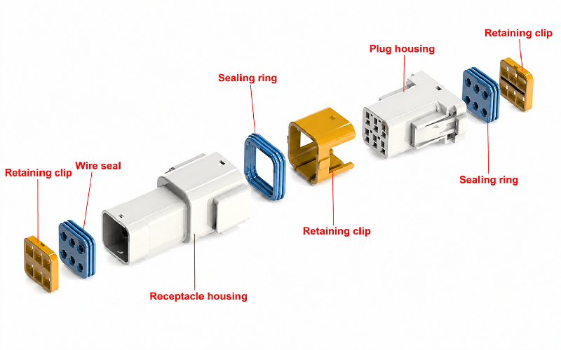
Exploded view


Waterproof plugs, retaining clips, sealing rings, terminals and male‑female housings work together to deliver reliable wire‑end mating, sealing protection and stable assembly.

Exploded view of HRB 3.0mm panel mount waterproof connector with seal, clip and terminals

Application Scenarios 


  • Outdoor Equipment

Reliable IP-rated waterproof connectors withstand outdoor humidity, dust and temperature fluctuations, delivering stable power & signal transmission for lawn mowers and outdoor gardening machinery.

  • Electric Motors

Robust structure and anti-vibration locking design guarantee long-term steady connection for industrial motors, effectively avoiding terminal loosening under continuous operation vibration.

  • Agricultural Drones

Compact layout + dustproof & waterproof performance adapts to farm complex working conditions, supporting safe power supply and signal control for plant protection drones during field spraying operations.

  • Outdoor Spotlights

Integrated sealing structure prevents rainwater & dust ingress, ensuring durable connection performance for landscape spotlights under long-term outdoor exposure.

  • Automotive Door Locks

Stable low-resistance contacts & anti-shock structure match automotive-grade requirements, realizing precise signal transmission for vehicle door lock control systems.

  • Smart Wheelchairs

Safe current carrying capacity and reliable locking structure support stable power output and control signal transmission, securing daily safe operation of mobility assist devices.

Technical FAQs


Q: What is the recommended wire strip length?

A: Reference value for wire strip length is 3.00±0.20mm.

The wire strip length depends on wire type and crimping method, and actual processing conditions shall be used to confirm the optimal strip length.

Do not nick or cut wire conductors during wire‑stripping operation.


Q: How to insert crimped terminal into housing correctly?

A: Before inserting the crimped terminal, align the orientation of housing and terminal for proper mating.

When the lock opening of the housing faces upward, the barrel‑seam side of the crimped terminal shall also face upward.

Do not rotate the terminal during or after insertion. Rotation may cause damage to rubber seals and housing.

Note: For terminal insertion: keep the smooth surface upward, anti‑key feature downward, and terminal barrel seam upward. Incorrect orientation will cause housing damage.


Q:What is the wiring recommendation for harness exiting from the connector?

A:Avoid sharp 90‑degree bends immediately at the connector wire exit. Sharp right‑angle bending will shorten harness service life and may lead to functional failures. Gradual, gentle cable bending is recommended during routing design.


Q:What should be noted during finished‑product inspection of harness assemblies?

A:

1. Use precision fixtures during wire inspection and electrical continuity testing to avoid prying the connector.

2. Perform continuity tests using the mating counterpart connector (e.g. receptacle for tab contact). Do not use non‑matching test 

pins. Replace test mating connectors periodically.

3. Replace any deformed or damaged connectors, contacts, sealing rings or wire seals with new parts directly, regardless of damage 

severity. Do not attempt repairs.

4. Verify wire seals are properly seated inside the housing.

5. Do not perform air‑blow testing, as this may dislodge sealing components.


Q:What are the storage and transportation precautions for connectors and harnesses?

A:

1. Store housings and crimped contacts under conditions: temperature 25 °C ± 5 °C, relative humidity ≤70% RH. Keep away from 

direct sunlight, moisture and dust. Sealing rings and wire seals are rubber‑based components. UV exposure will cause rubber aging, 

and dust contamination will degrade waterproof performance.

2. Handle stacked housings and wire harnesses with extra care during storage and transportation.


Q: What are the functions of latch‑lock female housing and panel‑mount female housing?


⒈Latch‑lock female housing (cable‑end)

Free‑hanging cable‑mount housing without panel mounting lugs. It locks to mating male housing via built‑in latch.

Function: Crimped onto cable ends for wire‑to‑wire connection. It moves together with wiring harness, not fixed to equipment 

chassis. Ideal for internal wiring, cable assemblies and peripheral extension cables.


⒉Panel‑mount female housing (equipment‑end)

Comes with mounting lugs, secured to equipment enclosure cut‑out by M4 bolts.

Function: Acts as a fixed external interface on device panel. It stays firmly mounted on chassis, accepting mating cable‑side plug. 

It provides sealing separation between inside and outside of equipment. Widely used for cabinet, motor housing and drone body 

ports.


Current Rating
10A AC DC Max.
Voltage Rating
250V AC DC
Temperature range
-40 ºC to +105 ºC
Contact resistance
20mΩ Max.
Insulation Resistance
1000MΩ Min
Withstanding Voltage
1500V AC/minute
Waterproof grade
IP67
Terminal Applicability
AWG22-18
Material
Housing: PBT
Seal ring/plug: Silicon
Contacts: Copper alloy
Finish
Tin
silver or Gold Plating Over Ni On Contact Area
Sealable
Yes
Previous: 
Next: 

QUICK LINKS

PRODUCTS

CONTACT US