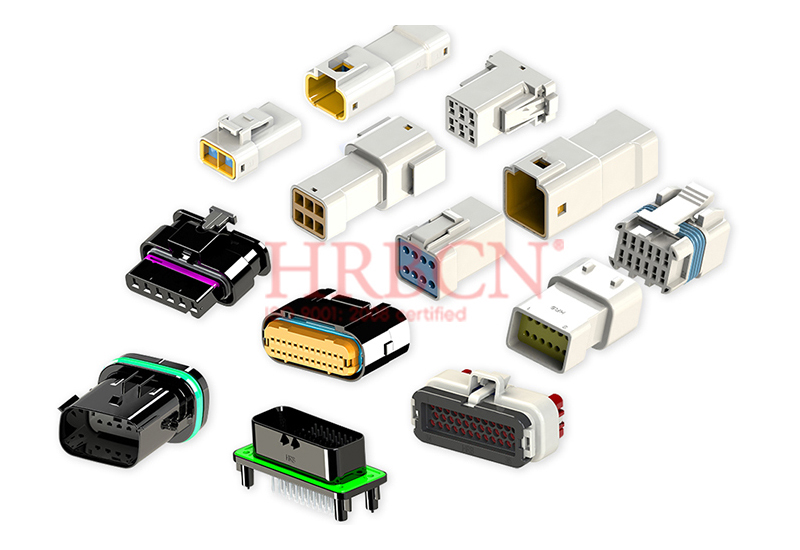
Every minute of industrial downtime costs thousands of dollars, often from just one bad connection. How do you build connector systems that stay reliable over time? The answer is a clear plan: figure out your signal and power needs, check environmental issues like heat, cold, dirt, and shaking, set the size, pin count, and contact size, then pick the right connectors for your gear. Locking parts stop accidental unplugging, and IP ratings show how well they block water and dust. This plan helps you choose tough connectors and wiring solutions that cut downtime and keep a steady link. Plan for enough plug-unplug cycles and easy setup to keep things working long-term. By doing this, you can design reliable connector systems that stay dependable in your equipment.
Key Takeaways
First, figure out your signal and power needs. This avoids expensive fixes later.
Pick a connector that fits your space and handles your electrical needs. This helps it work well and stay reliable.
Use locks, seals, and shields to guard against shaking, wetness, and signal noise. This keeps links steady.
Plan for the number of times you plug and unplug and make installation easy. This keeps the system reliable for a long time and saves time.
Talk to connector experts early on. They can help you pick the best option for your machine.
Assess Environmental and Signal Needs for Reliable Connector Systems
Before picking any parts, you need to know what your machine requires. A good connector design starts with two key questions: what signals must the connector carry, and what conditions will it face during use? Answering these early helps you avoid costly fixes and keeps things working well over time.
Identify Power, Data, and Signal Requirements
Every connection in your system has a job. Some links carry high current for motors or heaters. Others send low-level sensor signals. Still others move high-speed data between controllers and screens. Each type puts different demands on the connector. For power circuits, the contact material must handle high current without getting too hot. For signal and data lines, shielding is key to keep signals clear and block electromagnetic interference. Low-level analog signals need careful attention to contact resistance, since even a few milliohms can mess up readings.
HRB&HRBCN Connector's wire-to-wire connectors show this flexibility. These tough connectors support both low-signal and high-power uses. The strong locking designs also resist vibration and heat stress, making them good for tough environments.
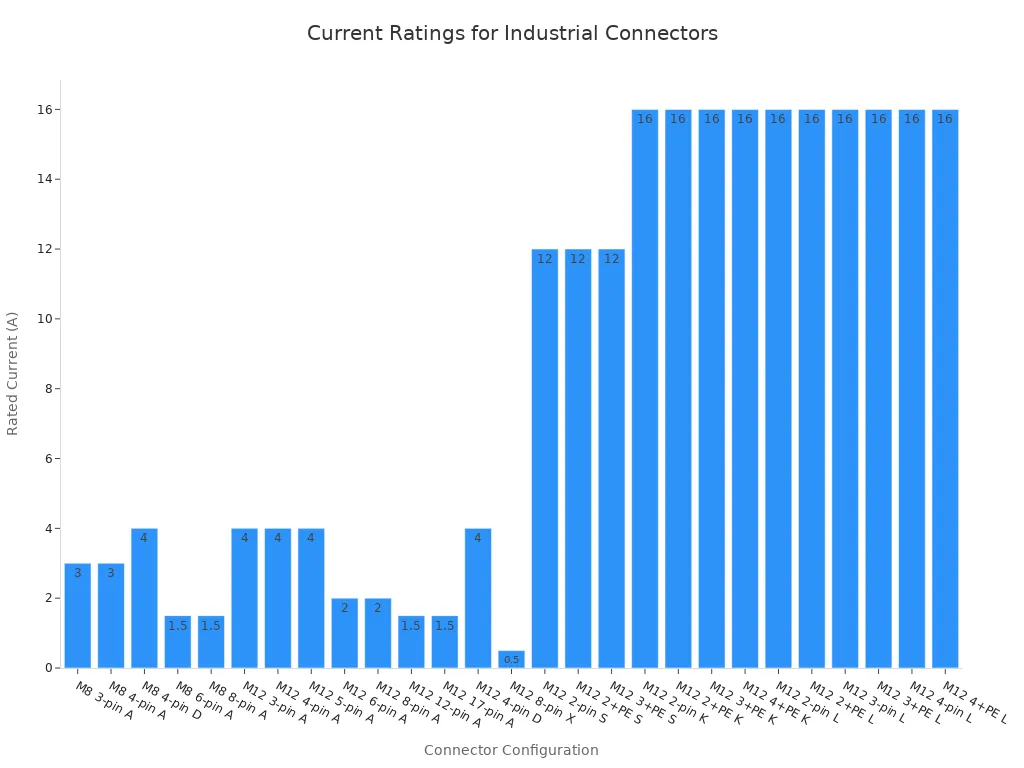
Industry standards give clear guidance on current ratings. The IEC standard for M8 and M12 connectors shows how pin count and coding affect current capacity. For example, an M12 connector with 3 pins and A-coding carries 4 amps, while an M12 connector with 2 pins and K-coding carries 16 amps. The chart below shows these ratings across different setups.
For data-heavy uses, you need rugged connectors that keep signal quality under vibration and heat stress. HRB&HRBCN wire-to-wire connectors support high-speed data with low signal loss and delays. They keep stable power even when the equipment shakes or heats up constantly.
Evaluate Temperature, Contaminants, and Vibration
The working environment decides which connectors will last long-term. Extreme temperatures can damage plastic housings and change contact spring force. Humidity and chemical contaminants speed up corrosion on exposed metal surfaces. Vibration causes fretting corrosion, a wear process that raises contact resistance over time.
HRB's IP67 waterproof power connectors show a clear example of environmental specs. These rugged connectors work in a temperature range of -55°C to +85°C. The IP67 rating under IEC 60529 ensures protection against dust and temporary water immersion. This makes them good for harsh places like washdown areas in food processing or outdoor gear exposed to rain.
The table below lists key specs for different HRB connector models:
Connector Model | IP Rating | Operating Temperature Range |
2.5mm Pitch Wire-to-Board (Right Angle) | IP67 (IEC 60529) | -55°C to +85°C |
2.5mm Pitch Automotive Waterproof | IP67 | -55°C to +85°C |
3.0mm Panel Mount Waterproof | IP67 | -40°C to +130°C |
Vibration testing follows known standards like MIL-STD-202. This standard checks how vibration affects parts in the frequency ranges and levels seen during field use. It shows possible problems when a part fails to meet vibration rules. When you pick connectors for tough environments, look for designs that have passed this testing. These parts use strong locking mechanisms and precise contacts to lower these risks.
By checking both signal needs and environmental conditions, you build a solid base for your design. This step ensures you choose parts with the right contact materials, shielding, sealing, and mechanical strength. The result is a system that delivers reliable power, data, and monitoring of system operations.
Specify Physical Dimensions and Contact Configurations
Industrial equipment enclosures rarely offer extra space. You must fit connectors into tight panels, crowded PCBs, or narrow cable paths. The physical dimensions of your connector system directly affect installation success and long-term reliability. To design reliable connector systems, you must consider two factors: the shell style that matches your mounting location and the pin count with contact size that matches your electrical loads.
Match Connector Size and Shell Style to Space Constraints
Every connector takes up real estate. Choose a shell style that fits your available space without compromising maintenance access. Panel-mount receptacles work well for fixed installations where you route cables through a bulkhead. In-line or cable-mount plugs suit movable sections or tight spaces where a panel cutout is impossible.
Compact IDC connectors demonstrate space-saving benefits. These connectors eliminate wire stripping, saving assembly time and reducing installation errors. The following table shows how pitch size affects your design options:
Pitch | Space-Saving Benefit | Key Context |
1.27mm | Saves board space by supporting more conductors in a compact footprint, enabling high-density signal routing | Best for dense PCB layouts, compact modules, servers, communication equipment, and industrial modules where space is limited |
2.54mm | Not the smallest option, but practical for standard industrial connections where service access and easier inspection matter | Suitable for industrial control panels, CNC systems, routers, switches, and test equipment where maintenance access is important |
The 1.27mm pitch lets you route many signals in a small area. This suits high-density designs like servers or communication modules. The 2.54mm pitch offers a balance between density and ease of access. You can probe and inspect connections without special tools.
Shell style also matters. Panel-mount receptacles use a fixed cutout with a threaded nut or flange. The iMINI C connector uses a 1 1/8-inch square receptacle with a 3/4 NPT mounting thread. The plug version has a maximum outer diameter of 1 1/4 inches. These dimensions tell you exactly how much space you need behind the panel.
Calculate Pin Count and Contact Size for Current and Signal Integrity
Connector pitch directly relates to current-carrying capacity. Larger pitch means bigger contacts, which handle more power. Smaller pitch means smaller contacts, which suit signal-level connections. Match pin count and contact size to your actual loads.
Consider HRB's wire-to-board connectors. The 5.08mm pitch terminal blocks suit high-current wire entry. The 2.5mm pitch connectors fit compact PCB layouts where you need moderate power and dense signal routing. Larger pitch connectors like 6.35mm or 10.0mm support high-power transmission for motors, heaters, or power supplies. Smaller pitches work for signal-level connections where current is low but density is high. The materials used in these contacts, such as brass and copper alloy with tin plating, ensure stable performance over time. These materials resist corrosion and maintain low contact resistance. This ensures stable power delivery even under high load conditions.
The relationship between pitch and current rating follows a clear pattern. A 3.5mm pitch connector typically carries up to 8 amps per pin. This rating stays the same whether you use 2, 3, or 4 pins. Pin count does not change per-pin current capacity. Each contact still carries its rated current independently.
5.08mm terminal blocks suit high-current wire entry. Current ratings vary by design: JST PH connectors carry 2 amps per pin, Molex Micro-Fit connectors carry 9 amps per pin, and DIN-5 connectors carry about 3 amps per pin. Larger pitch generally supports higher current-carrying capacity per pin, while smaller pitches have lower ratings.
Pitch 3.5mm: Contact current rating up to 8 amps (from TE product data)
For the same 3.5mm pitch, pin counts of 2, 3, and 4 all share the same 8 amp rating. Pin count does not affect per-pin current capacity
Manufacturers offer pitch options including 2.5mm and 5.08mm, implying varying current ratings
You must also consider voltage drop and heat buildup. Each contact generates heat proportional to the square of the current. In a multi-pin connector, heat from adjacent pins adds up. This can reduce the effective current rating. Always check the derating curve from the manufacturer.
Signal integrity requires attention to contact spacing. Closely spaced contacts can pick up crosstalk from adjacent signals. For high-speed data lines, maintain adequate separation between signal pairs. Use ground planes or shielding when needed.
The pin count you choose also affects installation effort. More pins mean more crimps, more insertions, and more potential failure points. Use the minimum number of pins that meets your circuit requirements. Reserve one or two extra pins for future expansion.
When you create cable assemblies, consider the connector's physical dimensions alongside the cable routing path. Cable assemblies with tight bend radii or heavy gauge wires need more space around the connector. Plan for strain relief and cable support to prevent mechanical stress on the contacts. This approach reduces failure rates and simplifies field service.
By matching shell style to your space and pin count to your loads, you build a connector system that fits physically and performs electrically. The next step is to add locking, sealing, and shielding mechanisms that protect the connection in harsh environments.
Select Locking, Sealing, and Shielding Mechanisms
Once you settle on physical dimensions and contact configurations, you must protect the connection itself. Vibration, moisture, and electromagnetic interference can all degrade performance over time. The right locking, sealing, and shielding mechanisms keep your system stable and secure.
Choose Locking and Keying to Prevent Disconnection and Mis-Mating
Vibration poses a constant threat to connector integrity. A loose connection causes intermittent signals, overheating, or complete system failure. You need a locking mechanism that withstands the mechanical stress of your application. Different mechanisms offer varying levels of protection:
Locking Mechanism | Primary Mechanism | Vibration Resistance Rating |
Thread-locking Compound | Chemical bonding/friction | High |
Split Lock Washer | Spring tension | Low to Moderate |
Star/Serrated Washer | Mechanical bite | Moderate to High |
Nylon Insert Nut | Polymer interference | High |
Castellated Nut & Pin | Positive mechanical stop | Extreme |
Screw connectors may loosen under vibration unless you pair them with locknuts, spring washers, or thread-locking compounds. Bayonet designs, with their locking cam features, resist axial loosening better, but radial or torsional stress can still affect them. HRB's IP67 waterproof connectors use housing-to-terminal locks for reliable performance. These locks prevent accidental disconnection even in demanding environments.
Many people find that a combination of proper initial torque and a medium-strength thread-locker provides the best balance for industrial machinery. Over-reliance on mechanical washers without verifying torque can still lead to failure if the vibration frequency matches the spring rate of the washer.
Keying prevents mis-mating, which causes costly rework and equipment damage. Two primary options exist:
Keying Option | Mechanism | How It Reduces Assembly Errors |
Color-keyed connectors | Brightly hued exteriors or color-coded graphics | Faster and easier visual matching of coordinating colors, allowing quick identification of mismatches |
Mechanically keyed connectors | Distinctive shape that only fits a corresponding connector and can only be inserted one way | Physically prevents incorrect mating or orientation; also acts as a polarization feature to prevent 180-degree rotation errors, especially in blind mating scenarios |
Mechanical keying uses unique shapes or protrusions to block incorrect insertion. Color-coded keying helps operators spot matching pairs quickly. Polarization features ensure correct orientation every time. These design elements reduce reliance on operator memory, eliminate rework, and boost confidence in blind mating scenarios.
Specify IP Ratings and EMI Shielding for Rugged Environments
Sealing protects internal contacts from water, dust, and chemicals. The IP rating system classifies this protection level. IP67, under IEC 60529, ensures dust-tight protection and temporary water immersion resistance. This rating suits washdown environments in food processing or outdoor installations exposed to rain. HRB's waterproof connectors meet this standard, operating from -55°C to +85°C with contact resistance at or below 10 milliohms. These rugged connectors maintain stable electrical performance even when submerged briefly.
Electromagnetic interference (EMI) disrupts data transmission and degrades signal quality. For data-intensive applications, you need shielding that blocks external noise and prevents emissions from escaping. HRB&HRBCN Connector offers solutions for telecom and data center applications requiring high-temperature and high-load protection. These rugged connectors provide dual protection against thermal stress and electrical interference, ensuring clean signal transfer in dense equipment racks.
Choosing the right protection mechanisms depends on your specific environment. Assess the vibration levels, moisture exposure, and EMI sources in your facility. Then select locking, sealing, and shielding that match those conditions. This systematic approach ensures your rugged connectors deliver long-term reliability in harsh environments. Every connection you protect today prevents a costly failure tomorrow.
Plan for Mating Cycles, Installation, and Long-Term Reliability
Account for Mating Cycle Life and Mechanical Endurance
Every connector has a limited number of times it can be plugged and unplugged. You need to know how often your equipment will be connected and disconnected over its life. This number helps you choose the right contact material and plating.
The base metal affects how well the contact keeps its spring force and how long it lasts. Brass works for low-cycle use. Phosphor bronze works better for high-cycle use. Tin plating is okay for general connectors, but not for very high-cycle use. Gold plating is better for high-cycle use. Tin works well in dry and low-level conditions, but it is not good for long-term high heat or high-cycle use.
HRB's IP67 waterproof connectors use tin-plated brass and copper alloy contacts. These materials resist rust and keep low contact resistance over time. For applications that need many plug-unplug cycles, you should use gold plating. Gold lasts longer than tin and handles higher temperatures.
Mechanical endurance testing follows EIA-364-09. This standard checks if the connector can handle many plug-unplug cycles without losing performance. After testing, the connector must show no major wear or damage. Its electrical performance must stay within set limits. Always check that your chosen connectors have passed this test.
Design for Ease of Installation and Field Serviceability
Installation speed affects your total system cost. Old methods like manual crimping take about 55 seconds per connection. Soldering takes about 100 seconds plus cleaning time. IDC connectors do not need wire stripping. They let you connect multi-conductor cables in seconds.
"The benefit of time and cost savings, plus ease of installation—because they simply clamp on with no need to strip wires—makes IDCs a very compelling choice." — Brad Blietz, 3M
HRB's IDC connectors support this fast assembly. They come in 1.27mm and 2.54mm pitches. They fit compact designs where space is tight. RAST connectors give extra installation benefits for automotive and industrial use:
Pre-terminated cable assemblies using IDC-style connections save installers a lot of time compared to old screw-terminal methods. They remove on-site termination steps and lower the risk of wiring errors. This cuts installation and maintenance costs.
HRB&HRBCN Connector holds ISO 9001, UL, VDE, and TS16949 certifications. These confirm steady quality and reliability for long-term industrial use. When you pick certified connectors, you lower downtime risk and make sure your design meets world standards. This focus on quality, plus good planning for mating cycles and easy installation, gives the high reliability your equipment needs.
Designing reliable connector systems demands deliberate choices at every step. You must assess environmental conditions, specify physical dimensions, select protection mechanisms, and plan for lifecycle demands. No single connector works best for every application. The optimal solution balances electrical performance, environmental protection, physical size, and cost.
Always consult manufacturer datasheets for specific performance data. HRB&HRBCN Connector offers both standard and customized interconnect solutions for unique application needs. Their connectors deliver reliable connection and power transmission across demanding industrial environments.
Engage with experienced connector manufacturers early in your design process. They ensure your requirements receive full understanding. This collaboration increases efficiency and reduces downtime. Your equipment deserves this attention. A thoughtful design yields increased efficiency and long-term reliability for your entire system.
FAQ
What IP rating do I need for washdown environments?
Pick IP67 for equipment that gets sprayed with water or briefly dunked. This rating, set by IEC 60529, keeps out dust and handles short dips. HRB's IP67 waterproof connectors work from -55°C to +85°C, so they fit food processing and outdoor gear.
How do I select the right pitch for my application?
Match pitch to your power needs. Bigger pitches like 6.35mm or 10.0mm move high power to motors and heaters. Smaller pitches such as 1.27mm or 2.5mm fit signal connections where space matters more than power. Always check the maker's derating curve for multi-pin setups.
What locking mechanism works best for high-vibration environments?
Housing-to-terminal locks stop vibration from pulling connections apart. HRB's IP67 connectors use this design to stay secure under stress. For screw-type connectors, add thread-locking compound or nylon insert nuts to stop loosening. Mechanical keying also blocks wrong hookups, cutting rework and damage.
How many mating cycles should I plan for?
Count how many times your gear plugs and unplugs during its life. Brass contacts last under 500 cycles. Phosphor bronze and copper alloy contacts handle 500 to over 5,000 cycles. For frequent plugging, choose gold-plated contacts. They resist wear and keep low resistance much longer than tin-plated ones.


