You need a secure electrical connection for your project. The best way depends on what you need. Crimping uses a tool to press a metal sleeve around a wire. Soldering joins metals by melting a filler metal. IDC Termination connects wires without removing insulation. Each method has its own benefits. Crimping works well with vibration. Soldering makes small joints. This method speeds up making many items. Picking the wrong method can cause failures that happen sometimes. Knowing these differences helps you choose the right way. This choice can make or break your project. Here is what you need to know. Crimping needs a special tool. Soldering needs careful heat control. IDC Termination uses a simple pressing tool. You must think about your work area and skill level. Each method has different strengths.
Key Takeaways
Crimping gives the strongest vibration resistance and works well in high-vibration environments.
Soldering makes small joints, but they break easily under physical strain and need trained workers.
IDC Termination gives the quickest and cheapest connections for making lots of products.
Pick your method by thinking about where the project will be used, how skilled you are, and how many you need to make.
For quick, dependable mass termination without stripping wire, IDC Termination is a great option.
Crimping: Overview and Key Traits
How Crimping Works and Its Main Benefits
Crimping makes a mechanical connection between a wire and a terminal. You use a special tool to press a metal sleeve around the wire. The pressure makes the metal flow around the wire strands. This creates a tight joint that resists corrosion and vibration. No heat or extra materials like solder are needed. You just strip the wire, put it into the terminal, and squeeze the tool.
Crimping is fast, which makes it great for making many items. Each connection can be done in less than one second. A skilled worker using a pneumatic tool can make 3,000 to 8,000 connections per hour. Soldering, by comparison, only makes 800 to 2,000 connections per hour. This saves a lot of labor time on production lines.
The strength of a crimped joint also impresses engineers. A properly crimped 18 AWG copper wire connection meets a minimum tensile strength of 142 N according to NASA-STD-8739.4A. Soldered joints do not have a similar number requirement because heat-affected zones and solder wicking create weak points. The cold-worked metal in a crimp keeps its full cross-section and grain structure. This gives you a reliable connection under mechanical stress.
Industry standards define the quality criteria for crimping. The IPC/WHMA-A-620 standard specifies visual and measurable attributes for three product classes. Class 1 suits general consumer electronics. Class 2 applies to industrial and automotive products. Class 3 covers high-performance aerospace and military systems. The standard requires a visible bellmouth at the front of the crimp, proper conductor visibility in the inspection window, and a defined gap between the conductor crimp and the insulation crimp. Class 3 demands tighter tolerances, such as crimp height within ±0.05 mm of the manufacturer's specification and 100% pull force testing. These rules ensure consistent, repeatable quality.
Common Drawbacks of Crimping
Despite its speed and strength, crimping has notable downsides. The biggest issue is the dependence on the operator's skill and tooling condition. Improper crimping causes about 25% of all wire harness field failures. This makes it the most common source of failure. The three main failure modes in high-vibration environments are under-crimping, over-crimping, and internal voids. Under-crimping leaves the wire loose, leading to pull-out or intermittent contact under vibration. Over-crimping crushes the strands, reducing current capacity and creating brittle fractures. Internal voids trap air, which promotes corrosion and eventual failure.
You also need a specific tool for every wire gauge and terminal combination. A mismatch between tool and terminal destroys the connection. The tool must be calibrated and maintained regularly. Any wear in the dies changes the crimp height and compromises quality. For small production runs, the cost of the tool can be hard to justify.
Another drawback is the lack of visual feedback. You cannot see the metal-to-metal contact inside the crimp. You rely on the crimp height measurement and pull force testing to verify quality. This requires extra inspection steps and equipment. If you work in a field repair environment, carrying a heavy pneumatic or hydraulic tool is inconvenient. Soldering or IDC termination may offer a simpler solution in those cases.
Soldering: Overview and Key Traits
How Soldering Works and Its Main Benefits
Soldering connects two metals by melting a filler metal called solder into the joint. You heat the connection with an iron, then apply solder that melts and flows around the wire strands. The solder cools to form both an electrical and mechanical bond. Unlike crimping, you do not need a heavy press tool. A basic soldering iron costs little and fits in a small kit.
The choice of solder alloy matters for your application. The table below shows common options:
Solder Material Type | Melting Point | Thermal Conductivity |
|---|
Tin-Lead (Sn-Pb) | 183°C | 50 W/(m·K) |
Lead-Free (Sn-Ag-Cu) | 217-220°C | 58 W/(m·K) |
High-Temperature (Sn-Ag) | 221°C | 70 W/(m·K) |
The 63/37 tin-lead alloy melts at a single point of 183°C, which makes it predictable for precise work. Lead-free SAC solder melts higher at 217°C but avoids the health concerns of lead. You should match the alloy to your operating temperature and any regulatory requirements.
A well-executed solder joint typically exhibits marginally lower electrical resistance compared to a crimped connection, but the difference is negligible for most practical applications.
This means you can trust a soldered joint for signal integrity without worrying about performance loss.
Common Drawbacks of Soldering
Soldering has serious weaknesses that you must consider. The joint depends entirely on the operator's skill with heat control. Too much heat damages the wire insulation or lifts a PCB pad. Too little heat creates a cold joint that looks dull and conducts poorly. You cannot easily inspect the internal quality of a solder joint without X-ray equipment.
The health risks demand attention. Solder fumes contain heavy metals that harm your body. Lead attacks the nervous system and kidneys. Tin can irritate your lungs and cause a condition called pneumoconiosis. Flux fumes add more danger.
Heavy metals present in solder fumes pose significant health risks to workers. Lead, a common component of solder alloys, is particularly notorious for its toxic effects on the nervous, kidney, and reproductive systems. Chronic exposure to low levels of lead can cause neurological impairments, cognitive deficits, and behavioral changes.
In addition to the exposure to solder fumes, solder fluxes containing fluoride and rosin based solder fluxes fumes can provoke lasting health symptoms. Inhalation of fluoride should be monitored due to the toxic nature of hydrogen fluoride and boron trifluoride. Both substances can cause eye, skin, nose, and throat irritation.
You need proper ventilation and fume extraction equipment. This adds cost and complexity to your workspace. Soldered joints also weaken under vibration. The solder itself can crack over time, especially in environments with constant movement. For high-vibration applications, crimping or IDC termination often proves more reliable.
IDC Termination: Overview and Key Traits
IDC Termination works differently than crimping or soldering. The connector has sharp, fork-like contacts that cut through the wire insulation when you press the wire in. This pushes the insulation aside and lets the metal touch the conductor directly. You do not need to strip the wire at all. This technology started in the 1960s and soon became common in telecom, automotive, and factory automation.
HRB&HRBCN IDC Connector Features
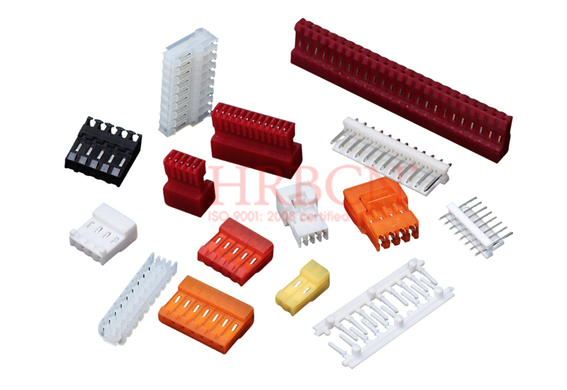
HRB&HRBCN Connector makes IDC parts built for speed and dependability. You push a wire into the connector slot, and the contact blades slice through the insulation to hold the conductor tightly. This removes the need for stripping tools and cuts setup time by a lot. You can finish dozens of wires in minutes instead of hours.
The connector works with many wire sizes, so you can use it across different jobs. Whether you need 1.27mm or 2.54mm pitch sizes, there is a matching option. The strong build uses tough materials that handle vibration and motion without coming loose. This makes the connector a good fit for moving environments where crimped or soldered joints might break.
The design also allows mass termination. You can connect many wires at once with a simple press tool. This speed helps on production lines where output matters. The connector keeps steady contact resistance through many mating cycles. For example, one common IDC connector family holds 20 mΩ contact resistance through 10 rated mating cycles in production, while a tougher prototyping version allows 25 cycles.
IDC Termination Drawbacks
IDC Termination has limits you should know about. Early versions only worked with solid wires. Makers later added support for stranded wire, but you must check that your wire type works before you start.
The number of mating cycles is another issue. Most IDC connectors can only handle a set number of insertions and removals. Once you connect a wire, repeated unplugging may hurt performance. This makes IDC a poor choice for jobs that need frequent disconnecting.
Old patents show more engineering problems. Early designs had trouble with heat and mechanical stress until Thomas International Ltd patented a one-piece metal connector with slotted beams in 1985. TE Connectivity later fixed bad crimping issues with a guide member design in 2003. These fixes made the parts better but also show how exact the manufacturing must be.
For insertion force reference, D-Sub connectors usually need a maximum of 3.3 newtons per contact. IDC connectors scale the same way with pin count, so high-density connectors need more force. You should plan for this when you design your assembly process.
Comparison: Key Differences Between Methods
Mechanical Strength and Vibration Resistance
You need to know how each method handles physical stress. Crimping makes the strongest mechanical bond. The cold-worked metal keeps its full shape and grain structure. This helps crimped joints do well in high-vibration places like car engines or factory machines. A good crimped connection stays tight because the metal sleeve grips the wire strands firmly. Soldered joints, however, get weaker with constant movement. The solder can crack over time. This makes soldering a bad choice for jobs with ongoing vibration. IDC Termination sits in the middle. The fork-like contacts grip the wire firmly and hold the conductor in place. The strong design handles vibration and motion without coming loose. For moving environments where wires shake, crimping and IDC Termination both beat soldering.
Repairability also matters. Crimped connections let you remove the terminal and crimp a new one. Soldered joints need desoldering, which can damage nearby parts with heat. IDC Termination usually allows only a set number of mating cycles. Once you press a wire in, repeated unplugging may hurt performance. Think about how often you need to disconnect and reconnect when picking your method.
Heat Sensitivity, Skill Level, and Tool Dependency
Heat sensitivity sets these methods apart in key ways. Soldering adds significant heat to the connection. You must control the temperature carefully. Too much heat damages wire insulation or lifts PCB pads. Too little heat creates a cold joint that conducts poorly. Crimping and IDC Termination use no heat at all. This makes them safer for heat-sensitive parts and removes the risk of thermal damage.
Skill level needs vary a lot. Soldering demands the highest skill. You must master temperature control, timing, and tinning techniques. A bad solder joint looks dull and fails quietly. Crimping needs moderate skill. You must pick the right tool and die for each wire gauge. The process is easy to standardize, but you must follow it exactly. IDC Termination needs minimal skill. You just press the wire into the connector slot. The contact blades cut through the insulation automatically. This lowers the chance of human error.
Tool costs and production speed also differ greatly. The table below shows these trade-offs:
Factor | IDC | Crimping | Soldering |
|---|
Cost | Most cost-effective for high-volume production | Moderately cost-effective | Most expensive due to labor costs |
Speed | Fastest | Moderately fast | Slowest |
Skill Level Required | Minimal | Moderate | High |
Soldering has low tool costs. You only need a soldering iron, solder, and flux. But the high skill need and slow manual process make it costly per connection in mass production. Crimping requires precision pliers or an automatic machine. Different terminals need matching dies, which raises the starting cost. However, the fast automated production speed lowers the cost per connection. IDC Termination proves most economical for high-volume runs. The streamlined process removes insulation stripping, soldering, and individual crimping. You save time and money because you cut out multiple manual steps. For large production lines, IDC Termination gives the lowest labor cost per connection.
Application Scenarios: When to Use Each Method
High Vibration and Field Repairs
In places with a lot of shaking, every connection is tested. You need a joint that stays tight when things move a lot. Crimping makes the strongest mechanical bond for these conditions. The cold-worked metal keeps its full shape inside. This helps it resist damage from repeated motion. You should pick crimping for engine areas, factory machines, and car systems. Soldered joints get cracks over time. The hard solder cannot handle the stress. So soldering is a bad choice for equipment that shakes or moves.
When fixing things in the field, you need simple tools and fast results. You might not have a heavy crimping tool or a soldering iron. IDC Termination gives a practical solution. You just push the wire into the connector slot. The contact blades cut through the insulation by themselves. You do not need to strip the wire or use heat. This makes field repairs faster and more dependable. The connector holds the wire tightly. You can trust it for most equipment that moves.
For moderate shaking, you have choices. Crimping is still best for important connections. The connector gives a good mix of speed and strength. The fork-like contacts grab the wire without solder. This design handles vibration well. You can use it for many jobs that have regular movement.
PCB Assembly and Cost-Sensitive Projects
PCB assembly requires soldering. The parts go directly on the board. You need exact connections between small pads and part leads. Soldering gives you that control. Crimping and IDC connectors do not work for through-hole or surface-mount parts. You must use solder for PCB work. This process lets you put parts close together. This saves important space on the board.
Projects that care about cost need a different way. You want to keep labor costs low. This method removes the need to strip wires and crimp each one. You connect many wires at once with a simple press tool. This cuts production time a lot. For large production runs, this method gives the lowest cost per connection. You save money on tools and labor.
Crimping works well for medium-sized projects. The tool cost may be harder to justify for small batches. But for production lines, the speed is worth it. Soldering needs skilled workers. This makes each connection cost more. You should think about the total cost. Include tools, labor, and inspection in your calculation. Each method has a different cost pattern. Pick the method that fits your production amount and budget.
Verdict: Best Choice for Common Use Cases
Best for General Hobbyists and Prototyping
You build circuits at home or test new ideas on a bench. Your projects change often. You need flexibility more than speed. Soldering gives you that freedom. A basic soldering iron costs little. You can rework joints easily. You can swap components without replacing entire connectors. For one-off prototypes, soldering makes sense. You control the heat. You see the joint form. You learn the skill quickly with practice.
Crimping also works for hobbyists who build wiring harnesses. You need a quality crimping tool. Cheap tools crush the wire instead of forming a proper connection. A good ratcheting crimper costs more but pays off. You get consistent results every time. The pull force table from IPC/WHMA-A-620 shows what a good crimp must withstand. For 22 AWG wire, your crimp must hold at least 31.1 newtons before the wire pulls out. For 18 AWG, that number rises to 66.7 newtons. You can test your work with a simple pull scale. This verification step builds confidence in your connections.
IDC Termination suits hobbyists who make many identical cables. Ribbon cable projects benefit most. You press the connector onto the wire with a small vise or hand press. No stripping. No soldering. No individual crimping. You finish a 10-wire connection in seconds. The trade-off is repairability. Once you press the connector, you cannot easily remove and reuse it. Plan your cable lengths carefully before you commit.
For prototyping, keep a soldering iron and a basic crimper on your bench. You will use both. Solder for PCB work and delicate joints. Crimp for connectors that face vibration or repeated handling. This combination covers most hobbyist needs without breaking your budget.
Best for Industrial and Professional Environments
Production lines demand speed, consistency, and traceability. Your choice affects your yield and your warranty costs. Soldering becomes expensive at scale. Skilled operators cost more. Each joint takes time. Inspection requires trained eyes or X-ray equipment. For high-volume wiring, soldering rarely wins.
Crimping dominates automotive and aerospace harness manufacturing. The standards are strict. Per IPC-A-620, the cross-section fill ratio for a crimp must land between 60% and 80%. This destructive test verifies proper conductor compression. It checks for voids that could cause corrosion later. You measure crimp height and width with micrometers. You verify tensile strength with pull testers. You perform cross-section analysis with crimp quality analyzers. You check for high or low crimps, insufficient insulation support, and damaged strands. These checks ensure every connection meets the required pull force. The table below shows minimum pull forces for common wire gauges:
Wire Gauge (AWG) | Minimum Pull Force (N) |
|---|
26 AWG | 13.3 |
22 AWG | 31.1 |
18 AWG | 66.7 |
14 AWG | 133.4 |
10 AWG | 222.4 |
These values come from IPC/WHMA-A-620. They define the minimum tensile force a crimped terminal must withstand before the wire pulls out. Your quality team must test samples regularly. This process costs time but prevents field failures.
For mass termination of flat ribbon cable or discrete wires, IDC Termination offers the fastest cycle time. You press many wires at once. The process removes stripping and individual crimping steps. HRB&HRBCN Connector builds IDC connectors for exactly this purpose. Their parts handle vibration well. They work with multiple wire gauges. They meet international certifications like UL and VDE. For production lines that need thousands of connections per day, IDC Termination delivers the lowest labor cost per joint.
No single method wins every scenario. Soldering suits prototypes and PCB work. Crimping excels in high-vibration environments with strict quality standards. IDC Termination provides unmatched speed for high-volume cable assembly. Match the method to your production volume, your quality requirements, and your environment. For quick, reliable mass termination, IDC solutions from HRB&HRBCN Connector stand as an excellent choice.
Crimping stands out for vibration resistance and ease of use. Soldering creates compact joints but weakens under mechanical stress. Fast, high-volume production works best with the insulation displacement method. No single method works for every situation. Your choice depends on your specific needs. Consider your project's environment, your skill level, and your production volume. Each method has strengths and weaknesses. For quick, reliable connections without stripping wire, IDC Termination from HRB&HRBCN Connector offers a strong solution. Evaluate each method carefully. Pick the one that matches your application requirements. The right choice saves time and prevents failures. Make your decision based on facts and your project goals. Match the method to your needs for the best results.
FAQ
Which connection method works fastest for mass production?
IDC Termination lets you connect many wires at once without stripping. A simple press tool finishes dozens of connections in seconds. This method saves the most labor time on high-volume lines.
Do I need special tools for each method?
Yes. Crimping requires a specific tool and die for each wire gauge. Soldering needs an iron, solder, and flux. IDC Termination uses a press tool. Tool costs vary widely between methods.
Can IDC connectors handle stranded wire?
Modern IDC connectors support stranded wire, but you must check compatibility first. Early versions only worked with solid wire. Always verify your wire type matches the connector specification before use.
Which method resists vibration best?
Crimping creates the strongest mechanical bond for vibration. The cold-worked metal keeps its full grain structure. IDC Termination also handles movement well. Soldered joints can crack under constant shaking.
Is soldering safe for beginners?
Soldering requires careful heat control and proper ventilation. You must avoid inhaling heavy metal fumes. IDC Termination or crimping may be safer choices for new users with less experience.


