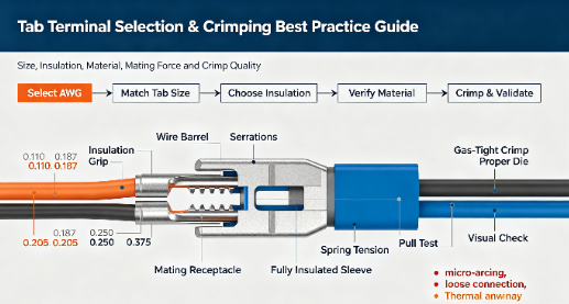
Improper terminal selection introduces severe operational risks to electrical systems. A mismatched connection increases electrical resistance, leading directly to thermal runaway. In high-vibration environments, this oversight often results in catastrophic system failure. Engineers and procurement teams constantly navigate a fragmented landscape of wire gauges, tab dimensions, form factors, and insulation materials. This complexity makes it difficult to specify components that balance safety, mechanical reliability, and spatial efficiency.
Selecting the correct components requires a strict evaluation of mechanical and electrical demands. Relying on generic connectors for specialized applications compromises system integrity. This guide serves as a technical framework for evaluating terminal specifications. It provides actionable methods to match insulation types to environmental demands. You will learn how to standardize procurement for electrical assemblies, ensuring every connection meets rigorous performance thresholds.
Key Takeaways
Precision Sizing is Non-Negotiable: Matching the American Wire Gauge (AWG) and exact tab width/thickness (e.g., 0.250" x 0.032") is critical to prevent micro-arcing and mechanical pull-out.
Insulation Dictates Application: A fully insulated terminal is required for dense enclosures or high-voltage applications to prevent accidental short circuits, whereas partially insulated or non-insulated variants suit controlled, low-risk environments.
Form Factor Solves Spatial Constraints: Selecting between straight, flag, and piggyback orientations is just as critical as sizing when designing for tight enclosures.
Material Science Drives Performance: Base metals (brass vs. copper) and plating (tin vs. silver) must be evaluated against the specific conductivity requirements and corrosive exposure of the deployment environment.
Tooling Consistency is Mandatory: The reliability of a terminal is directly proportional to the calibration of the crimping tool and the use of the correct, manufacturer-specified die profile.
How Tab Terminals Work
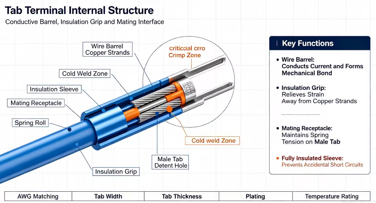
A standard Tab Terminal includes a mating section, wire barrel, and insulation sleeve. Male tabs connect with female terminals, while straight, flag, and piggyback designs are available for different wiring layouts and space requirements. A reliable connection requires low electrical resistance, secure wire retention, proper insulation, and good contact between the male and female terminals. Correct terminal sizing and spring tension help prevent loose connections, overheating, and connection failure.
Why Use Fully Insulated Terminals?
Densely packed control panels present significant electrical hazards. Automotive wiring harnesses and HVAC systems operate in incredibly tight spaces where components constantly shift due to thermal expansion and mechanical vibration. Exposed conductive surfaces in these environments invite disaster. A dropped tool, a shifting wire, or a loose component can easily bridge the gap between exposed metal parts. This bridging causes immediate short circuits. The resulting damage ranges from blown fuses and damaged logic boards to severe electrical fires that destroy entire equipment racks.
A Fully insulated terminal eliminates this specific hazard by completely encapsulating both the wire crimp zone and the mating interface. The dielectric material extends past the metal edges of the receptacle. When fully mated with an insulated male tab, zero bare metal remains exposed. This complete dielectric barrier prevents accidental contact with adjacent wires, grounded chassis components, or maintenance tools. The nylon or PVC housing acts as a physical bumper, absorbing impacts and preventing the internal metal from deforming or shorting out against nearby conductive surfaces.
Specifying fully insulated options yields direct safety and compliance outcomes. It drastically reduces short-circuit risks in vibrating machinery where wire harnesses frequently rub against metal frames. Live-maintenance procedures become significantly safer for technicians troubleshooting active panels. Furthermore, these components simplify compliance with strict electrical codes. Inspectors evaluating systems against NEC or OSHA standards actively look for exposed conductors. Utilizing fully encapsulated connections demonstrates adherence to modern safety protocols, passes inspections faster, and reduces long-term liability for the manufacturer.
How to Choose the Right Tab Terminal Size
Wire Gauge (AWG) Compatibility
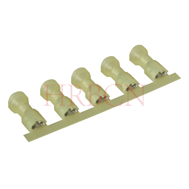
Choosing a terminal that matches the wire gauge (AWG) is important for a reliable crimp. Common color codes include red for 22–18 AWG, blue for 16–14 AWG, and yellow for 12–10 AWG wires. The terminal should also match the wire type, as stranded and solid wires may require different terminal or crimp designs. Always check the terminal specifications before crimping to ensure the correct wire size and type are used.
Tab Width and Thickness Standards
Tab terminals are available in standard widths such as 0.110", 0.187", 0.205", 0.250", and 0.375". The 0.250" size is commonly used in industrial and automotive applications, while smaller sizes are often used in electronics and appliances. Both tab width and thickness must match the female terminal correctly. An incorrect size can create a loose or overly tight connection, leading to poor contact, overheating, or terminal damage.
| Standard Width (Inches) | Standard Thickness (Inches) | Common Application Environments |
| 0.110" | 0.020" / 0.032" | Micro-switches, relays, small electronics |
| 0.187" | 0.020" / 0.032" | Appliance motors, speakers, low-amp circuits |
| 0.205" | 0.020" / 0.032" | Specialty automotive, specific relay blocks |
| 0.250" | 0.032" | Industrial controls, automotive harnesses, HVAC |
| 0.375" | 0.040" | High-current power supplies, heavy machinery |
Amperage and Current Carrying Capacity
The terminal must meet or exceed the maximum current load of the circuit. A connection acts as a physical bottleneck for electrical flow. If the terminal's ampacity limit is lower than the circuit's peak current, the metal will overheat. This thermal stress degrades the insulation, weakens the spring tension of the receptacle, and accelerates oxidation. Over time, the resistance compounds until the connection fails completely, often taking the surrounding wire jacket with it.
A terminal's physical size and base metal dictate its ampacity limit. This limit is entirely independent of the attached wire gauge. You can crimp a 10 AWG wire capable of carrying 30 amps into a specific terminal. However, if that terminal's mating interface is only rated for 15 amps, the connection becomes a critical failure point. Always verify the maximum current rating of the specific terminal series, ensuring it aligns with the upstream breaker or fuse rating of the circuit.
Mating Force and Retention Requirements
Insertion and extraction forces define the mechanical feel and security of the connection. Insertion force must be low enough to allow manual assembly without causing repetitive strain injuries to workers on the production line. Extraction force must be high enough to prevent accidental disconnection during operation. Repeated connections degrade the spring tension over time. Most standard terminals are rated for a specific number of mating cycles before the retention force drops below acceptable limits, requiring replacement of the female receptacle.
Detent mechanisms provide necessary mechanical locking. Male tabs often feature a small hole or a stamped dimple near the tip. Female receptacles feature a corresponding raised bump inside the rolled edge. When mated, the bump snaps into the hole or dimple. This mechanical interlock prevents the connection from vibrating loose under mechanical stress. Applications subject to heavy vibration rely entirely on these detent mechanisms for long-term stability.
Terminal Materials and Insulation Types
Base Metal and Plating Selection
Brass is commonly used for terminals because it is durable, cost-effective, and resistant to wear, while copper alloys provide better electrical conductivity and are often used for higher-current applications. Plating helps protect terminals from oxidation and corrosion. Tin plating is common for industrial and automotive applications, while silver or gold plating may be used when higher conductivity or reliable signal transmission is required.
Insulation Material Comparison
PVC is a common and cost-effective insulation material for standard applications, but it may become brittle in cold temperatures or crack under mechanical stress. Nylon offers better flexibility, temperature resistance, and resistance to oils and chemicals, making it suitable for industrial and automotive applications. Heat shrink insulation provides additional moisture protection and strain relief, making it a good choice for marine, outdoor, and other environments exposed to water or salt spray.
| Insulation Material | Max Temperature | Key Characteristics |
| Vinyl (PVC) | 105°C (221°F) | Cost-effective, standard flexibility, prone to cold-cracking. |
| Nylon | 125°C (257°F) | Solvent resistant, highly durable, resists splitting during crimping. |
| Heat Shrink | 105°C to 135°C | Waterproof seal, internal adhesive, maximum strain relief. |
| Non-Insulated | 150°C+ (302°F+) | Used in extreme heat environments, requires external heat shrink if sealing is needed. |
Storage and Shelf-Life Considerations
Proper storage helps maintain terminal insulation quality. UV exposure, high humidity, and very dry conditions can damage PVC or nylon insulation and may also cause metal parts to oxidize. Terminals should be stored in a clean, controlled environment away from direct sunlight, excessive moisture, and extreme dryness to maintain insulation flexibility and consistent crimp quality.
Environmental and Safety Requirements
Temperature and Voltage Ratings
Temperature and voltage ratings are important when choosing terminal insulation. PVC is commonly rated up to 105°C, while nylon can typically handle temperatures up to 125°C. Standard insulated terminals are often rated for 300V to 600V, depending on the product. Higher-temperature or higher-voltage applications may require specialized insulation or fully insulated terminal designs.
Vibration and Mechanical Stress
Vibration can weaken wire connections over time, especially where the wire exits the crimp barrel. Double-crimp terminals help reduce this risk by securing both the wire strands and the outer insulation. This provides better strain relief and makes the connection more reliable in machinery, vehicles, and other high-vibration applications.
Industry Certifications
Terminal certifications help confirm that components meet relevant safety and environmental requirements. UL and CSA certifications are commonly used in North America, while RoHS addresses restricted hazardous substances. Automotive and international applications may also require relevant SAE, IEC, or DIN standards. Checking the required certifications before purchasing helps reduce compliance issues and component selection problems.
Conclusion
Audit your current wire harness specifications to identify mismatched tab thicknesses and incorrect AWG pairings.
Request detailed manufacturer spec sheets to verify the ampacity limits and temperature ratings of your chosen connectors.
Standardize your facility's crimping tools to ensure die profiles match the specific terminal brands in your inventory.
Implement mandatory pull-tests on sample crimps before authorizing bulk procurement or assembly runs.
Transition to fully encapsulated nylon terminals for all high-density panels to eliminate accidental short-circuit risks.
FAQ
Q: What is the difference between a fully insulated terminal and a partially insulated terminal?
A: A fully encapsulated terminal covers both the wire barrel and the entire mating interface with dielectric material. When connected, no bare metal is exposed. A partially insulated terminal only covers the wire barrel, leaving the metal blade or receptacle exposed after mating.
Q: How do I know what size tab terminal I need?
A: You must measure two distinct elements. First, determine the AWG of your wire to select the correct barrel size (Red, Blue, or Yellow). Second, measure the exact width and thickness of the mating male tab (e.g., 0.250" wide by 0.032" thick) to select the matching receptacle.
Q: When should I use a flag tab terminal instead of a straight terminal?
A: Use a flag terminal in tight enclosures where a straight wire exit would hit a panel or cover. The 90-degree angle routes the wire parallel to the mating surface, preventing severe bending, mechanical strain, or wire fatigue.
Q: What is a piggyback tab terminal?
A: A piggyback terminal is a combination component. It features a standard female receptacle for mating to a post, while also featuring an integrated male tab on its back. This allows you to stack multiple connections onto a single terminal block post.
Q: Can I use a standard crimping tool on a fully insulated terminal?
A: No. Standard tools often crush or pierce the extended insulation. You must use a ratcheting crimper with an asymmetrical die specifically designed for fully encapsulated terminals to ensure a gas-tight crimp without ruining the dielectric barrier.
Q: Why are tab terminals color-coded?
A: The colors represent industry-standard wire gauge (AWG) compatibility. Red indicates 22-18 AWG. Blue indicates 16-14 AWG. Yellow indicates 12-10 AWG. This system allows technicians to quickly identify the correct part for the wire they are using.
Q: What happens if I use a 0.250" female terminal on a 0.187" male tab?
A: The connection will be physically loose because the spring rolls will not make adequate contact with the narrower blade. This lack of tension causes high electrical resistance, micro-arcing, heat generation, and eventually an electrical fire.


