Technical FAQs
Q: Should I select a 90° right-angle header or a 180° straight header for HRB M63505 waterproof wire-to-board connector?
A: Selection depends on PCB layout, internal enclosure space and wiring routing requirements; electrical performance, waterproof grade (IP67) and current/voltage ratings are identical for both styles.
⒈180° Straight Header (Vertical pin)
Applicable scenarios:
Sufficient vertical clearance above the PCB; wires extend straight forward along the vertical direction of PCB surface.
Control boxes, automotive battery modules and outdoor equipment with abundant internal wiring space, easy for straight plugging & maintenance.
Densely arranged multi-row connectors requiring uniform forward wiring.
Advantages: Simple assembly, intuitive insertion operation, less wire bending stress, convenient post-market inspection and disassembly.
Disadvantages: Occupies vertical height inside the housing; not recommended for slim, height-limited equipment.
⒉90° Right-Angle Header (Horizontal pin)
Applicable scenarios:
Compact, thin enclosures with limited vertical internal height, such as built-in automotive cameras, electric motorcycle controllers and mini outdoor waterproof modules.
Wires need to run horizontally along the PCB surface or sidewall of the housing to avoid extrusion by the enclosure cover.
Vibration-prone vehicle equipment: horizontal wiring disperses wire pulling force away from PCB solder joints to reduce pin breakage risk.
Advantages: Greatly saves vertical installation space, neat side routing, reduces excessive wire bending.
Disadvantages: Requires reserved horizontal side clearance for wiring; slightly lower operability during blind insertion in narrow cavities.
Q: How to insert crimped contacts into the connector housing?
A: Before inserting crimped contacts, orient both the connector housing assembly and contacts for proper mating. Position the housing with its locking feature facing upward, and align the contact so that its barrel‑seam side also faces upward.
Do NOT rotate the contact during or after insertion; rotation may cause damage to the rubber seal or crack the housing.
⒈In case of receptacle contact
Step①: Tilt the crimped contact. Rest its tip on the seal‑equipped mating cavity. Expand the seal opening carefully to avoid damaging the cavity top surface. Press the contact tip onto the rubber seal plate to insert the box section of the contact.
Step②: Straighten the crimped contact, then insert the tip of its box section. Push the contact all the way in — do not pry or apply undue force — until you hear a click.
Step③: After hearing an audible‑click upon full contact insertion, gently pull the wire to confirm the contact is securely locked by the housing lance.
⒉In case of tab contact
Step①: Insert the crimped contact straight into the housing. Avoid damaging the periphery of the seal‑fitted cavity with the contact tip. Tilting the contact toward the housing locking side during insertion may cut the rubber seal plate and cause the contact tip to enter a neighboring cavity. Refer to the figure below; pay close attention to insertion orientation.
Step②: Push the crimped contact all the way in. Do not pry or apply excessive force, stop when you hear an audible click.
Step③: After hearing an audible click upon full insertion, gently pull the wire to confirm the crimped contact is securely locked by the housing lance.
Q: How to remove crimped contacts from the housing after incorrect insertion
A: If a crimped contact is inserted into the wrong cavity, removal shall only be performed by qualified personnel. Do not reuse the housing or rubber seal plate once they have been used.
Insert the extraction tool between the crimped contact and housing from the mating side. Push the tool in direction ① to disengage the housing lance from the contact locking hook. Then pull the wire in direction ② to remove the contact from the housing.
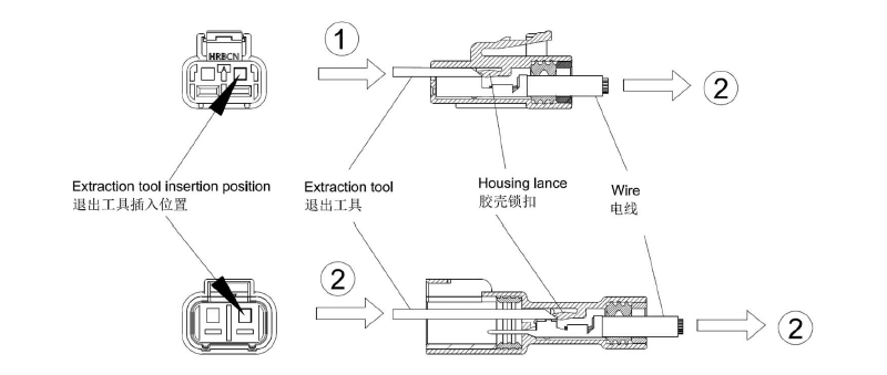
Precautions:
Prior to removal, confirm that the tip of the extraction tool is fully inserted into the clearance between the crimped contact and the housing lance.
Before reusing a removed crimped contact, confirm that it is free of deformation. If any deformation is detected on the contact, replace it with a new one (re‑crimping is required).
Do not pry the crimped contact using the extraction tool. If prying occurs during removal, replace the contact with a new one.
When removing a receptacle contact, if the extraction tool is mistakenly inserted into the gap of the contact mating section, replace the contact with a new one regardless of insertion depth.
If the crimped contact cannot be removed even by gently pulling the wire, do not apply force to pull it out. Restart the removal procedure from the beginning.
If the crimped contact cannot be removed even by gently pulling the wire, do not apply force to pull it out. Restart the removal procedure from the beginning.


