You are here: Home » Products » Waterproof Connector (IP67, IP68, IP69K) » 6.35mm Pitch Waterproof Connector » HRB 6.35mm Pitch Panel Mount Wire To Wire Waterproof Electrical Connectors

Related News

content is empty!

loading

Share to:
facebook sharing button
twitter sharing button
line sharing button
wechat sharing button
linkedin sharing button
pinterest sharing button
whatsapp sharing button
kakao sharing button
snapchat sharing button
telegram sharing button
sharethis sharing button

HRB 6.35mm Pitch Panel Mount Wire To Wire Waterproof Electrical Connectors

HRBCN 6.35mm pitch panel mount wire-to-wire waterproof electrical connectors are with IP67 dustproof & waterproof rating conforming to IEC 60529. The series supports single/dual row configurations with 2, 3, 4 pins per row, equipped with a dual locking system combining main lock and TPA secondary lock to prevent terminal withdrawal during vibration.
Constructed with PBT housing, silicone integrated sealing plug and phosphor bronze contacts with nickel-tin plating, these connectors deliver stable low contact resistance (-40℃~+130℃ wide temperature range), withstand 600V voltage and carry up to 30A maximum current. Available with green/blue color-coded seal plugs for different wire insulation outer diameters, they are widely applied in construction machinery, AGV robots, refrigerated transport, mining lighting, energy storage and marine humid salt-spray environments, fully RoHS compliant with customizable harness assembly service.
  • Fully RoHS & REACH Compliant
  • UL&cUL Certified
Availability:
Quantity:
  • A-M63501WF, A-M63502WF

  • HRBCN

  • 8536909000

P/N definition


A-M63501WF-NXN-W-X

           ①         ② ③ ④ ⑤

①M63501WF: HRB series, Plug

②1: single row; 2: dual row

③N: Number of Pins per row 2/3/4pin

④Color: W: White

⑤Seal Plug Color:

-1: Green (Wire insulation OD 2.65-3.1mm)

Blank: Blue (Wire insulation OD 2.9- 4.0mm)


A-M63502WF-NXN-W-X-P

           ①         ② ③ ④ ⑤ ⑥

①M63502WF: HRB series, Receptacle

②1: single row; 2: dual row

③N: Number of Pins per row 2/3/4pin

④Color: W: White

⑤Seal Plug Color:

-1: Green (Wire insulation OD 2.65-3.1mm)

Blank: Blue (Wire insulation OD 2.9- 4.0mm)

⑥P: With panel mount


Core Features


  • IP67 waterproof & dustproof performance for outdoor and wet environments

  • 6.35mm fixed contact pitch, compact housing structure for space-limited assembly

  • Dual locking system (main lock + TPA secondary lock) to stop terminal withdrawal

  • Silicone integrated sealing ring for stable long-term waterproof effect

  • Phosphor bronze terminals with Ni+Sn plating, low contact resistance and corrosion resistance

  • Wide operating temperature range: -40℃ ~ +130℃

  • Multiple pin count options to cover different power & signal connection requirements

  • RoHS compliant, factory direct supply with customizable harness assembly service


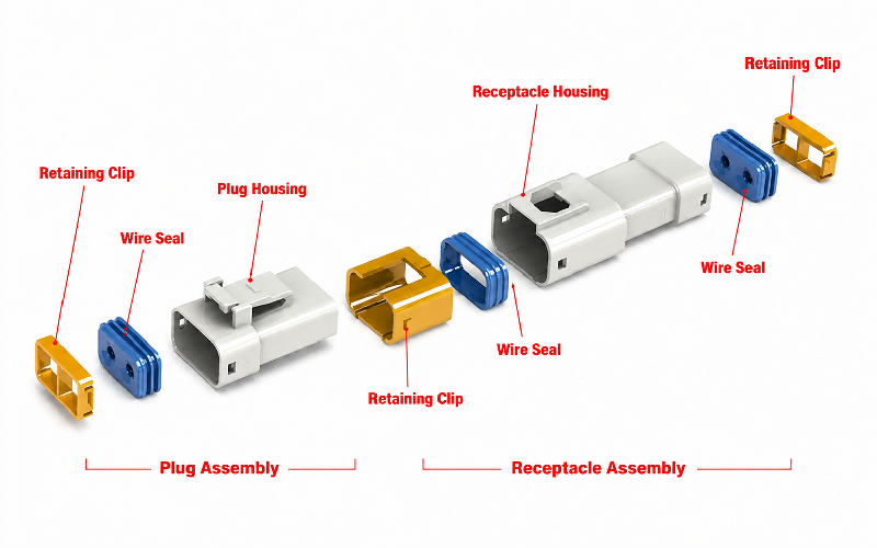
Exploded view


Wire seals, retaining clips, sealing rings, terminals and housings cooperate synergistically to deliver secure mating performance, reliable sealing protection and stable long-term assembly performance.


6.35 waterproof connector exploded view


Application Scenarios 


  • Construction Machinery

Suitable for excavators and engineering vehicles, resisting vibration and outdoor harsh weather.

  • AGV Logistics Robots

Stable power connection for automated warehouse handling equipment.

  • Refrigerated Transport Vehicles

Adapt to long-term low-temperature operating environments.

  • Mining Lighting

Waterproof and dustproof design fits damp underground tunnel conditions.

  • Energy Storage Equipment

Supports high-power transmission for outdoor energy storage systems.

  • Marine Equipment

Capable of coping with humid and salt-spray marine environments.


Technical FAQs


Q: How to insert crimped contacts into the connector housing?

A: Before inserting crimped contacts, orient both the connector housing assembly and contacts for proper mating. Position the housing with its locking feature facing upward, and align the contact so that its barrel‑seam side also faces upward. 

Do NOT rotate the contact during or after insertion; rotation may cause damage to the rubber seal or crack the housing.


⒈In case of receptacle contact

Step①: Tilt the crimped contact. Rest its tip on the seal‑equipped mating cavity. Expand the seal opening carefully to avoid damaging the cavity top surface. Press the contact tip onto the rubber seal plate to insert the box section of the contact.

Step②: Straighten the crimped contact, then insert the tip of its box section. Push the contact all the way in — do not pry or apply undue force — until you hear a click.

Step③: After hearing an audible‑click upon full contact insertion, gently pull the wire to confirm the contact is securely locked by the housing lance.


⒉In case of tab contact

Step①: Insert the crimped contact straight into the housing. Avoid damaging the periphery of the seal‑fitted cavity with the contact tip. Tilting the contact toward the housing locking side during insertion may cut the rubber seal plate and cause the contact tip to enter a neighboring cavity. Refer to the figure below; pay close attention to insertion orientation.

Step②: Push the crimped contact all the way in. Do not pry or apply excessive force, stop when you hear an audible click.

Step③: After hearing an audible click upon full insertion, gently pull the wire to confirm the crimped contact is securely locked by the housing lance.


Q: How to remove crimped contacts from the housing after incorrect insertion

A: If a crimped contact is inserted into the wrong cavity, removal shall only be performed by qualified personnel. Do not reuse the housing or rubber seal plate once they have been used.

Insert the extraction tool between the crimped contact and housing from the mating side. Push the tool in direction ① to disengage the housing lance from the contact locking hook. Then pull the wire in direction ② to remove the contact from the housing.
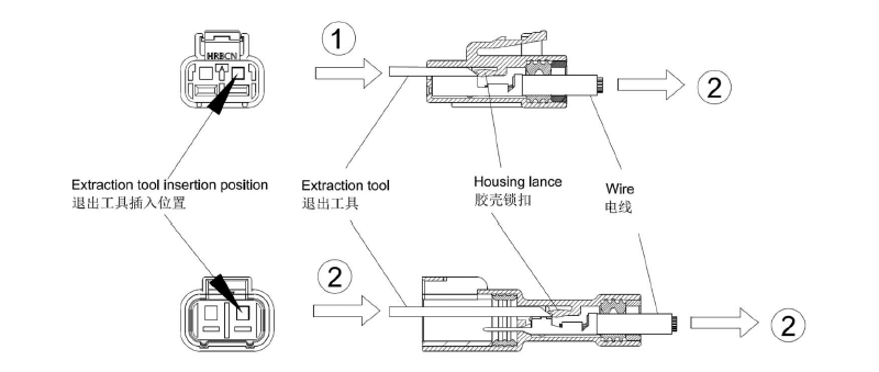
How to extract contact from housing ?


Q: What is the correct procedure for mating the male and female housings of this waterproof connector?

Step Align the locking tab on the male housing with the locking lever of the receptacle housing, as illustrated in the figure below. Perform mating along the mating axis; do not pry.

Step②: Mate the two housings until the lock is fully engaged. Verify secure housing locking by gently pulling the housing. (An audible click will be heard when the locking lever and locking tab are properly engaged.)
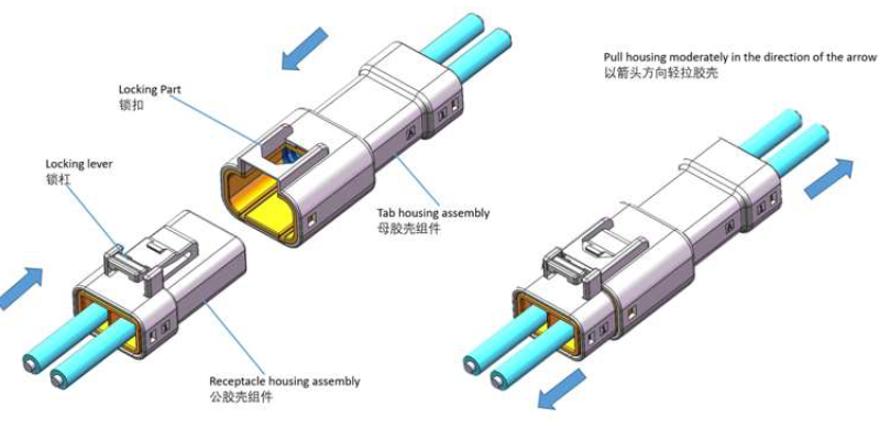
Assembly diagram of A-M63501 and A-M63502


Current Rating
30AMax.(AWG10)
25A Max.(AWG12)
Voltage Rating
600V AC DC
Temperature range
-40 ºC to +130 ºC
Contact resistance
≤20mΩ Max
Insulation Resistance
1000MΩ Min
Withstanding Voltage
2200V AC/minute
Waterproof grade
IP67 of IEC 60529
Terminal Applicability
AWG10
AWG16-12
AWG18-16
Material
Contacts: Copper alloy
Housing: PBT
Seal ring/plug: Silicon
Finish
Tin Plating Over Ni On Contact Area
Sealable
Yes
Previous: 
Next: 

QUICK LINKS

PRODUCTS

CONTACT US