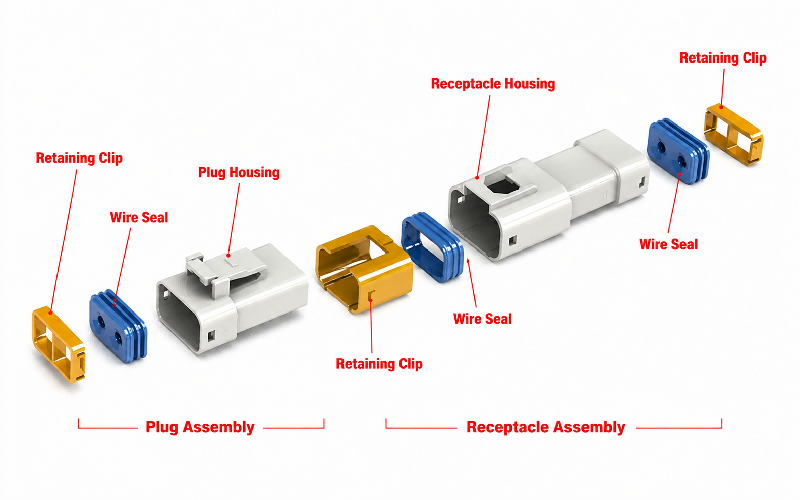
Technical FAQs
Q: How to insert crimped contacts into the connector housing?
A: Before inserting crimped contacts, orient both the connector housing assembly and contacts for proper mating. Position the housing with its locking feature facing upward, and align the contact so that its barrel‑seam side also faces upward.
Do NOT rotate the contact during or after insertion; rotation may cause damage to the rubber seal or crack the housing.
⒈In case of receptacle contact
Step①: Tilt the crimped contact. Rest its tip on the seal‑equipped mating cavity. Expand the seal opening carefully to avoid damaging the cavity top surface. Press the contact tip onto the rubber seal plate to insert the box section of the contact.
Step②: Straighten the crimped contact, then insert the tip of its box section. Push the contact all the way in — do not pry or apply undue force — until you hear a click.
Step③: After hearing an audible‑click upon full contact insertion, gently pull the wire to confirm the contact is securely locked by the housing lance.
⒉In case of tab contact
Step①: Insert the crimped contact straight into the housing. Avoid damaging the periphery of the seal‑fitted cavity with the contact tip. Tilting the contact toward the housing locking side during insertion may cut the rubber seal plate and cause the contact tip to enter a neighboring cavity. Refer to the figure below; pay close attention to insertion orientation.
Step②: Push the crimped contact all the way in. Do not pry or apply excessive force, stop when you hear an audible click.
Step③: After hearing an audible click upon full insertion, gently pull the wire to confirm the crimped contact is securely locked by the housing lance.
Q: How to remove crimped contacts from the housing after incorrect insertion
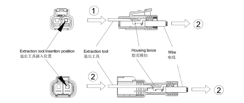
A: If a crimped contact is inserted into the wrong cavity, removal shall only be performed by qualified personnel. Do not reuse the housing or rubber seal plate once they have been used.
Insert the extraction tool between the crimped contact and housing from the mating side. Push the tool in direction ① to disengage the housing lance from the contact locking hook. Then pull the wire in direction ② to remove the contact from the housing.
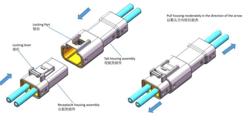
Q: What is the correct procedure for mating the male and female housings of this waterproof connector?
Step①: Align the locking tab on the male housing with the locking lever of the receptacle housing, as illustrated in the figure below. Perform mating along the mating axis; do not pry.
Step②: Mate the two housings until the lock is fully engaged. Verify secure housing locking by gently pulling the housing. (An audible click will be heard when the locking lever and locking tab are properly engaged.)
Q: What are the differences between single row and dual row connector housings, and how to make the correct selection?
1. Core Differences Between Single Row & Dual Row Housings
Single Row Housing
Structure: Pins arranged in one straight line; compact lateral width, simple wiring routing
Electrical feature: Limited pin count (usually 2/3/4 pins for your 6.35mm series); lower total current load per unit side space
Assembly advantage: Easy alignment during mating, low blind insertion error rate; convenient terminal insertion & extraction operation
Space characteristic: Narrow horizontal occupation, needs enough vertical installation height
Dual Row Housing
Structure: Pins arranged in two parallel rows; higher pin density within limited housing width
Electrical feature: Supports more pins (4/6/8 pins etc.) to integrate multi-circuit signals/power; centralized wiring for multiple circuits
Assembly note: Requires precise anti-miskey alignment; slightly higher operation requirement for terminal loading
Space characteristic: Saves vertical installation height, suitable for narrow vertical space scenarios
2. Standard Selection Rules
Choose Single Row Housing If:
Only 2~4 circuit signals/power are required, no need for more pin positions
The equipment has narrow horizontal installation space, limited side reserved width
On-site assembly needs simple operation, frequent maintenance & disassembly
Independent separate wiring for each circuit is required, avoiding cross interference of multi-row wiring
Choose Dual Row Housing If:
More than 4 circuits need to be integrated, central wiring layout is required
Equipment enclosure has limited vertical height, need to increase pin density without widening housing width
Multi-channel power & signal transmission is needed for modules like controllers, AGV main control units
Unified harness management is required to reduce scattered single-row connector occupation