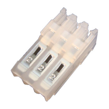
Wire-to-board IDC connectors connect insulated wires to a PCB interface without pre-stripping each wire at the IDC termination point. For small home appliances, this can remove a wire preparation step and support a more controlled harness assembly process.
However, a successful connection depends on the complete system: the wire, IDC connector, mating header, assembly tooling, and installation conditions.
This guide explains what engineers and buyers should check when evaluating wire-to-board IDC connectors for small home appliances.
How Does a Wire-to-Board IDC Connection Work?
In an IDC termination, a specially designed contact slot displaces the wire insulation and engages the conductor. The wire must match the contact’s approved specification and be seated using the required process.
For a separable wire-to-board arrangement, the assembly commonly includes:
An IDC connector terminated to the wires.
A compatible header mounted on the PCB.
The mating interface between the connector and header.
This distinction matters during process planning. A solderless wire termination does not mean that the PCB header requires no soldering. The board-side mounting process must be checked separately.
IDC also describes the termination method, rather than a particular cable format. Some connectors accept individual insulated wires; others are designed for specified ribbon cables.
Where IDC Connectors May Fit in Small Appliance Wiring
Small appliances can contain several connection types, each with different requirements. Potential locations to evaluate include control-panel harnesses, switch wiring, sensor leads, and connections between internal modules and a control PCB.
These are application examples for design review, rather than confirmation that one IDC model suits every circuit.
Before selecting a connector, identify:
The function of each circuit.
Operating voltage and current.
The wire specification.
Local temperature and environmental exposure.
Available installation space.
Assembly and service requirements.
A connector suitable for one control circuit should not automatically be used for a heater, motor, or other load circuit.
Match the Wire Before Selecting the Connector
Check More Than AWG
Wire gauge is only part of IDC compatibility. Two wires with the same AWG can have different conductor constructions and insulation dimensions.
Provide the supplier with:
| Wire information | What to confirm |
| Conductor size | AWG or cross-sectional area |
| Conductor construction | Solid or stranded, including strand details where required |
| Insulation material | Compatibility with the approved termination |
| Insulation outside diameter | Fit with the contact and wire guide |
| Wire identification | Exact wire manufacturer and specification where available |
Do not substitute a different wire solely because its nominal gauge matches.
Confirm the Exact Ordering Variant
An IDC product family may offer several wire-size options. This does not mean that every individual connector accepts the full family range.
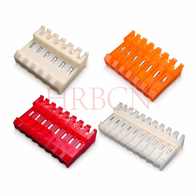
HRB’s M7060-N-C 3.96mm feed-through IDC connector, for example, includes wire-size-specific ordering options. Confirm the selected variant against the actual production wire.
If the wire changes during sourcing, review compatibility before releasing the substitution to production.
Select the IDC Connector and PCB Header Together
Verify the Complete Mating Pair
Matching pitch is necessary, but it is not enough to establish compatibility.
Check the approved mating part number, position count, contact arrangement, housing geometry, polarization, and locking features.
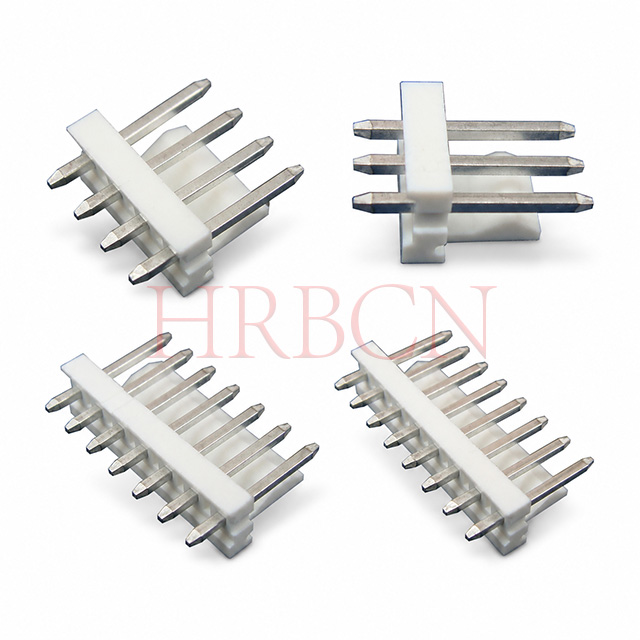
HRB’s 3.96mm vertical PCB header illustrates the board-side component of a wire-to-board connection. Its drawing should be reviewed together with the proposed IDC connector drawing.
Do not approve a substitution based only on a similar photograph or the same nominal pitch.
Review Electrical Requirements as an Assembly
Check the ratings and conditions applicable to the IDC connector, mating header, and wire combination.
The PCB header’s published current rating should not be treated as the rating of the complete harness connection. Ask which operating conditions and test data apply to the proposed combination.
For circuits with startup peaks or changing loads, include those conditions in the design review rather than relying only on a nominal operating value.
Plan Cable Routing Inside the Appliance
Compare Closed-End and Feed-Through Layouts
Connector geometry affects how the harness fits inside the enclosure.
A closed-end connector terminates the wire within the housing. A feed-through design permits the specified wire routing through the connector.
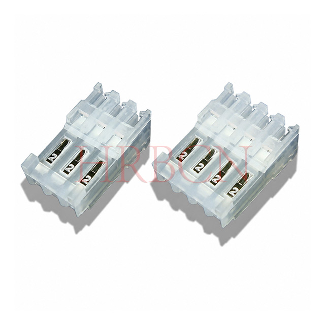
For a compact wiring layout, HRB’s M2051R-N-R 2.54mm closed-end IDC connector provides another configuration to evaluate.
Choose the layout using the product drawing and harness requirements. A feed-through design should not automatically be treated as approval for any proposed daisy-chain circuit.
Check the Full Installation Space
Review more than the connector body dimensions. Include:
Mated connector height and width.
Wire exit direction.
Cable bend space.
Access for mating and releasing the connector.
Clearance from adjacent components.
Harness position after the enclosure is closed.
A harness that fits on an open bench may become pinched or tensioned during final assembly.
Separate Retention from Cable Support
A connector lock helps retain the mating interface. Cable support manages forces transmitted through the harness.
Do not assume that a locking ramp provides strain relief for the wire termination. Confirm any built-in support features and plan additional cable restraint where the assembly requires it.
Route the harness so that normal installation does not pull continuously on the connector or PCB header.
Account for Heat, Moisture, and Movement
Conditions inside an appliance can differ from the surrounding room.
During design review, consider nearby heat sources, possible condensation or splashes, moving parts, and vibration. Check whether the selected connection has documentation relevant to its actual location.
Connector pitch alone does not prove electrical spacing compliance or environmental suitability. A larger pitch does not automatically make a connection suitable for every higher-voltage circuit.
Likewise, a dust cover is not evidence of waterproof protection, and a locking feature is not a substitute for documented vibration performance.
Keep application approval separate from a general description such as “for home appliances.”
Control the IDC Assembly Process
1. Verify Parts and Wire
Before termination, confirm the connector variant, wire specification, circuit count, and assembly drawing.
Use clear identification to prevent similar-looking parts from being mixed.
2. Set Up the Specified Tooling
Use the termination tool, fixture, or assembly method specified for the connector.
Do not assume that one tool works across different pitches or product families. Obtain the required setup and acceptance information before production.
3. Position and Terminate the Wires
Check wire order, orientation, alignment, and seating.
Follow the specified termination depth or dimensional criteria. Applying more force is not a substitute for correct tooling and positioning.
4. Inspect the Harness
Check for incorrect wire positions, incomplete seating, damaged housings, and improperly fitted covers or retention features.
Define electrical and mechanical checks using the applicable product and assembly requirements.
5. Check the Final Appliance Installation
After mating the harness to the PCB, verify that it is fully seated and correctly routed.
Check that enclosure assembly does not trap the wires, obstruct the lock, or place excessive load on the header.
Common Wiring and Assembly Problems
| Problem | Items to investigate |
| Intermittent connection | Wire compatibility, termination depth, alignment, and mating condition |
| Wire does not seat correctly | Insulation diameter, conductor specification, connector variant, and tooling |
| Cracked or distorted housing | Tool alignment, fixture support, and process settings |
| Incorrect circuit connection | Wire order, connector orientation, and assembly identification |
| Connector under tension | Harness length, routing, and cable restraint |
| Unexpected heating | Circuit load, contact condition, wire selection, and applicable ratings |
Use this table to guide investigation. Determine acceptance or corrective action from the requirements for the specific assembly.
What to Confirm Before Volume Purchasing
Before placing a production order, prepare a connection specification that includes:
IDC connector and mating header part numbers.
Circuit count and wiring order.
Complete wire specification.
Electrical operating conditions.
Installation temperature and environmental exposure.
Required connector orientation and wire routing.
Termination tooling and inspection requirements.
Expected quantity and packaging needs.
Confirm sample assembly results before approving a new connector-and-wire combination for volume use.
Price comparisons should include tooling and assembly requirements as well as the connector purchase price.
Frequently Asked Questions
1. Does a wire-to-board IDC connector eliminate PCB soldering?
Not necessarily. IDC removes pre-stripping at the wire termination point. A separate PCB header may still require soldering or another specified board-mounting process.
2. Can the same IDC connector accept any wire with the correct AWG?
No. Conductor construction, insulation material, and insulation outside diameter may also affect compatibility. Use the approved wire specification.
3. Does a locking ramp prevent all vibration-related problems?
No. It helps retain the mating interface, but vibration performance also depends on the complete assembly, cable support, and application conditions.
4. Can wires be removed and reinserted during repair?
Do not assume that retermination is permitted. Disconnecting a mating connector is different from removing a wire from its IDC contact. Follow the manufacturer’s repair instructions.
5. What should I send HRB for an appliance connector inquiry?
Provide the wire specification, circuit count, mating interface, electrical requirements, installation conditions, and expected quantity. Include an assembly drawing or existing part numbers when available.
Discuss Your Appliance Wiring Requirements with HRB
The right IDC connection starts with a defined wire, mating interface, and assembly process.
Contact HRB with your appliance wiring requirements and proposed installation layout. Request the relevant connector drawings, mating information, and termination requirements to evaluate the configuration before ordering.


