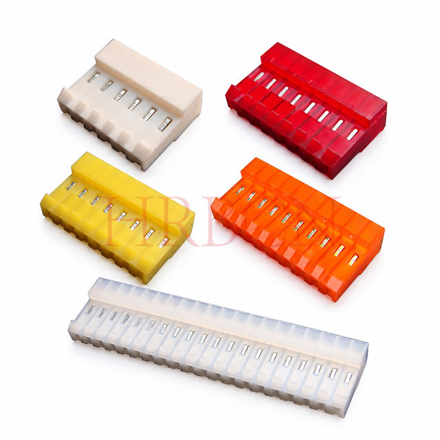
An IDC connector, short for insulation displacement connector, makes an electrical connection without stripping the insulation from each wire before termination. The insulated wire is pressed into a specially designed contact slot, which displaces the insulation and engages the conductor.
For engineers and buyers, the key is matching the connector to the wire and assembly process. Wire size, insulation dimensions, contact design, and termination depth all affect the finished connection.
This guide explains how IDC connectors work, how common designs differ, and what to check before selecting one.
How Does an IDC Connector Work?
An insulation displacement connection uses a controlled metal slot to establish contact with the conductor beneath the insulation. The slot edges displace the insulating material as the wire enters.
The conductor deforms locally within the contact zone. When the specified wire and termination process are used, this can produce a gas-tight metal-to-metal interface.
Here, “gas-tight” describes the local electrical contact interface. It does not mean that the connector housing is waterproof or that the complete assembly is sealed against moisture.
Main Components
Depending on the design, an IDC connector may include:
IDC contacts: Slotted metal contacts that engage the conductors.
Insulating housing: Holds the contacts in position.
Wire guides: Help align wires with the termination slots.
Cover or retention features: Secure the assembly where provided.
Mating interface: Connects to a compatible header or connector.
Check the individual product drawing to confirm which features are included.
What Happens During IDC Termination?
The exact procedure depends on the connector series. A typical assembly workflow includes the following steps.
1. Confirm Wire Compatibility
Check the approved conductor size, conductor construction, insulation material, and insulation outside diameter. Matching AWG alone is not enough to confirm compatibility.
2. Position the Wire
Place the wire in the specified guide or fixture. For multi-position assemblies, verify the circuit order and connector orientation before termination.
3. Apply the Specified Termination Process
Use the tool, fixture, or assembly method specified for the connector. Seat the wire to the required depth rather than judging the connection by appearance alone.
4. Check the Completed Assembly
Inspect wire position, seating, housing condition, and any cover or retention features. Use the applicable manufacturer requirements to define electrical and mechanical acceptance checks.
IDC removes the pre-stripping step at the termination point, but it still requires a controlled assembly process.
Common IDC Connector Designs
IDC describes a termination method, rather than one connector shape. Different designs serve different wiring arrangements.

Ribbon Cable IDC Connectors
Ribbon cable designs align multiple conductors with an array of contacts. Check cable conductor spacing, connector geometry, circuit count, and orientation together.
Discrete-Wire IDC Connectors
Discrete-wire designs terminate individual insulated wires. They allow the wiring arrangement to be considered separately from a ribbon cable format.
For available product options, explore HRB’s IDC connector range.
Closed-End and Feed-Through Designs
A closed-end design terminates the wire within the connector. A feed-through design permits the specified wire routing through the connector.
These arrangements affect cable layout and assembly access. Confirm the intended routing in the product drawing before ordering.
Polarized Designs
Polarizing features help control mating orientation when used with the correct mating part. HRB’s M2051R-N-R closed-end IDC connector is one example of a design with polarizing tabs.
Confirm the mating part number as well as the connector dimensions.
IDC vs. Crimp and Solder Connections
The best termination method depends on the wire, production process, and service requirements.
| Selection factor | IDC termination | Crimp termination | Solder termination |
| Wire preparation | No pre-stripping at the IDC contact point | Typically requires stripping | Typically requires stripping |
| Connection process | Insulated wire enters a contact slot | Contact barrel is compressed around the conductor | Solder joins the prepared conductor to the termination |
| Process controls | Wire compatibility, alignment, and insertion depth | Wire preparation, tooling, and crimp dimensions | Preparation, heat input, and joint quality |
| Procurement checks | Approved wire and assembly method | Approved wire, terminal, and crimp tool | Approved materials and soldering process |
IDC can remove a wire preparation operation. However, it should not be selected on assembly speed alone. Compare the complete process, including tooling, inspection, cable routing, and repair requirements.
How to Select an IDC Connector
Use the following checklist to narrow down suitable parts.
Match the Complete Wire Specification
Provide the supplier with:
Conductor size in AWG or cross-sectional area.
Solid or stranded construction.
Insulation material.
Insulation outside diameter.
Cable format and conductor spacing, where relevant.
Do not assume that a contact approved for one wire construction accepts another.
Confirm Pitch, Circuit Count, and Mating Parts
Pitch is the center-to-center distance between adjacent contact positions. It is only one part of connector compatibility.
Also check the number of positions, housing shape, mating orientation, polarization, and mating part number. Two connectors with the same pitch are not automatically interchangeable.
Review Electrical and Environmental Requirements
Check the selected part’s current, voltage, and temperature ratings against the application.
If the assembly will face moisture, vibration, or repeated handling, request documentation relevant to those conditions. Do not infer environmental protection from the IDC termination method itself.
Review Tooling and Production Requirements
Before committing to a production quantity, confirm:
The required termination tool or fixture.
Assembly instructions and inspection criteria.
Access for wire insertion and connector mating.
Cable support and routing.
Whether the termination is approved for rework.
Ask for the documentation for the exact part number being considered.
Common IDC Assembly Problems to Check
When a connection fails inspection or behaves intermittently, review the process before changing the connector.
| Potential issue | What to check |
| Wire does not seat as expected | Approved insulation diameter, conductor size, and tool setup |
| Inconsistent electrical connection | Wire alignment and specified insertion depth |
| Damaged housing | Tool compatibility, fixture alignment, and assembly settings |
| Incorrect circuit order | Wire placement, orientation, and assembly identification |
| Stress at the termination | Cable routing and specified support or retention features |
Use these checks to guide investigation. The final acceptance decision should follow the connector manufacturer’s requirements.
Frequently Asked Questions
1. Do IDC connectors work with both solid and stranded wire?
IDC designs exist for both. However, an individual contact may support only specified wire constructions. Check the approved wire specification for the exact part.
2. Can an IDC connector be reused?
Do not assume that it can. Disconnecting a mating connector is different from removing a wire from an IDC termination. Follow the manufacturer’s instructions for retermination or replacement.
3. Does an IDC connector need a special tool?
Many designs require a specified tool or fixture, while some use a tool-less assembly method. Confirm the requirement before choosing a part.
4. Does a gas-tight IDC connection make the connector waterproof?
No. Gas-tight contact describes the local metal-to-metal interface. Waterproof protection requires a separate connector or enclosure design with documented environmental performance.
5. What should I send a supplier when requesting an IDC connector quotation?
Include the wire specification, circuit count, pitch, mating part details, electrical requirements, installation conditions, and expected order quantity. A drawing or sample can help clarify the required configuration.
Discuss Your IDC Connector Requirements with HRB
Selecting an IDC connector starts with the wire and mating arrangement.
Review HRB’s IDC connector products, then contact HRB with your wire specification, circuit count, required pitch, and application details. Ask for the relevant drawing and termination requirements before confirming your selection.


