| Availability: | |
|---|---|
| Quantity: | |
M2050-N-C(180°)
HRB
8536909000
M2050-N-C(180°)
① ② ③④ ⑤
①M2050: HRB series
②N: Number of pins: 2-24
③C: Housing color, see below chart explanation
④Without R(Blank): Without polarizing tabs
⑤180°: Feed through
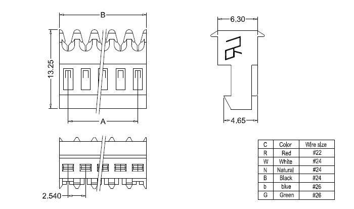
| C | Housing color | Wire size |
| R | Red | AWG22 |
| W | White | AWG24 |
| N | Natural | AWG24 |
| B | Black | AWG24 |
| b | blue | AWG26 |
| G | Green | AWG26 |

| Part No. | Dimensions | Part No. | Dimensions | ||||
| UL94V-2 | Circuits | Dim: A | Dim: B | UL94V-2 | Circuits | Dim: A | Dim: B |
| M2050-2-C(180°) | 2 | 2.54 | 5.08 | M2050-10-C(180°) | 10 | 22.86 | 25.40 |
| M2050-3-C(180°) | 3 | 5.08 | 7.62 | M2050-11-C(180°) | 11 | 25.40 | 27.94 |
| M2050-4-C(180°) | 4 | 7.62 | 10.16 | M2050-12-C(180°) | 12 | 27.94 | 30.48 |
| M2050-5-C(180°) | 5 | 10.16 | 12.70 | M2050-13-C(180°) | 13 | 30.48 | 33.02 |
| M2050-6-C(180°) | 6 | 12.70 | 15.24 | M2050-14-C(180°) | 14 | 33.02 | 35.56 |
| M2050-7-C(180°) | 7 | 15.24 | 17.78 | M2050-15-C(180°) | 15 | 35.56 | 38.10 |
| M2050-8-C(180°) | 8 | 17.78 | 20.32 | M2050-16-C(180°) | 16 | 38.10 | 40.64 |
| M2050-9-C(180°) | 9 | 20.32 | 22.86 | M2050-17-C(180°) | 17 | 40.64 | 43.18 |
Key Features
No polarizing tabs offers greater mating flexibility.
IDC termination allows quick, solder-free assembly.
Positive alignment improves connection reliability.
Reduces risk of mismatching during installation.
Compatible with standard 2.54 IDC connector systems.
Robust housing provides secure cable retention.
UL94V-2 flame retardant housing, RoHS compliant
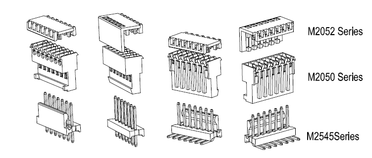
Designed to pair with M2052 series housing covers, effectively preventing dust, moisture and foreign debris from damaging exposed contact terminals.
M2050-N-C(180°): Indirect PCB mating; mates with M2545 and M2545R series PCB headers to achieve reliable wire-to-board interconnection.

Q1: What wire sizes are supported by 2.54 IDC connectors?
A: Typically supports 22–26 AWG, depending on the specific part number.
Q2: Is soldering required for termination?
A: No. IDC technology provides a solder-free wire termination process.
Q3: What is the function of the feedthrough design?
A: It allows signals to pass through the connector for daisy-chain or inline wiring applications.
Q4: What are the design implications of using 2.54 IDC Feed Through without polarizing tabs?
A: Without polarizing tabs, the connector does not provide mechanical keying, meaning it can be inserted in multiple orientations if multiple identical headers exist. This requires careful PCB layout or mechanical guidance in the system design to prevent mis-mating.
Q5: Are special tools required for assembly?
A: Hand tools or bench termination tools are recommended for consistent wire insertion.
Q6: What applications are these connectors commonly used in?
A: Industrial controls, appliances, instrumentation, and low-voltage electronic systems.
Q7: How is mis-mating risk managed in designs without polarizing tabs?
A: In applications without polarizing features, mis-mating is typically controlled through housing design, color coding, labeling, or fixed-position mounting structures. It is generally recommended only for systems where connector orientation is inherently constrained or assembly is well controlled.
Procurement FAQs
Q1: What are the main benefits of IDC connectors compared to crimp solutions?
A: Faster assembly, fewer components, and reduced labor costs.
Q2: Are feedthrough and polarized versions available in multiple circuit counts?
A: Yes. Various positions and configurations are available to meet different design requirements.
Q3: Can these connectors help reduce assembly time?
A: Yes. IDC termination enables rapid mass termination without wire stripping.
Q4: Are polarized versions interchangeable with standard 2.54 IDC connectors?
A: They are designed for compatibility within the 2.54 IDC system while adding mating protection.
Q5: What factors should be considered when selecting a connector?
A: Circuit count, wire gauge, polarization requirements, and application environment.
Q6: Are these connectors suitable for high-volume production?
A: Yes. Their simple termination process supports efficient large-scale manufacturing.
PLC modules, I/O interface boards – transmit signals from sensors or actuators.
Signal bus headers – for connecting multiple signal lines quickly and flexibly.
Reason: System design ensures correct signal alignment, so polarization is not required.
Patch panels, control boards, distributed I/O systems.
Reason: Frequent board-to-board connections, but signals are clearly defined by system design.
Test jigs, development boards, prototype setups.
Reason: Users may need freedom to reconfigure pin arrangements, so non-polarized connectors are preferred.
Small PCB-to-PCB or module-to-module signal/low-power connections.
Reason: In controlled designs, orientation is known, and polarization is not essential.