
The main difference between 2.54mm and 3.96mm IDC connectors is the center-to-center spacing between adjacent contact positions. A 2.54mm pitch provides closer contact spacing, while a 3.96mm pitch places the contacts farther apart.
However, pitch alone does not determine current capacity, wire compatibility, mechanical strength, or suitability for harsh environments. These properties must be checked for the specific connector and its mating parts.
For engineers and buyers, choosing between the two starts with the existing interface, available space, wire specification, and electrical requirements.
What Does Pitch Mean in an IDC Connector?
Pitch is the distance between the centers of adjacent contact positions. It is not the overall connector width, wire diameter, or housing height.
An IDC connector uses insulation displacement termination to connect an insulated wire to a contact without pre-stripping the wire at the termination point. The approved wire and assembly method depend on the connector design.
A useful distinction is that IDC describes a termination method. It does not mean every IDC connector is designed for ribbon cable. Discrete-wire IDC connectors terminate individual insulated conductors.
When reviewing a drawing, distinguish between:
Mating contact pitch.
Cable conductor spacing, where applicable.
Row spacing in multi-row connectors.
Overall housing dimensions.
PCB mounting dimensions.
These measurements serve different purposes and should not be treated as interchangeable.
2.54mm vs 3.96mm IDC Connectors at a Glance
| Selection factor | 2.54mm IDC connector | 3.96mm IDC connector |
| Contact pitch | 2.54 mm | 3.96 mm |
| Contact spacing | Closer spacing | Wider spacing |
| Contact-row span at the same position count | Shorter | Longer |
| Overall installation space | Check the housing, header, and cable routing | Check the housing, header, and cable routing |
| Compatible wire | Depends on the exact contact and housing variant | Depends on the exact contact and housing variant |
| Current and voltage ratings | Confirm from the selected part documentation | Confirm from the selected part documentation |
| Locking and polarization | Depend on the selected design | Depend on the selected design |
| Direct interchangeability | Cannot directly replace a 3.96mm interface | Cannot directly replace a 2.54mm interface |
Neither pitch is universally better. The correct choice is the one that meets the complete connection requirements.
Key Differences That Affect Connector Selection
Contact Spacing and Installation Space
For the same number of positions in a single row, 2.54mm pitch gives a shorter distance between the first and last contact centers.
This contact-center span can be calculated as:
Contact-center span = (number of positions − 1) × pitch
For a six-position single-row connector:
At 2.54mm pitch, the span is 12.70 mm.
At 3.96mm pitch, the span is 19.80 mm.
These figures describe the contact-center span only. They are not overall housing dimensions.
Before choosing a connector for a compact enclosure, also check housing width, mated height, header orientation, wire exit direction, and clearance for assembly.
Wire Compatibility
Do not select an IDC connector by pitch and AWG alone.
The supplier may also specify conductor construction, insulation material, insulation outside diameter, and an approved wire range for each contact variant.
For example, HRB identifies its M2051R-N-R 2.54mm closed-end IDC connector as a discrete-wire design with polarizing tabs.
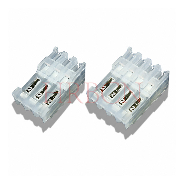
For comparison, HRB’s M7060-N-C 3.96mm feed-through IDC connector uses wire-size-specific variants.
These examples show why the exact ordering code matters. A connector family may include several wire options, but one individual part should not be assumed to accept every wire listed for the family.
Current and Voltage Ratings
A larger pitch does not automatically establish a higher current rating.
Current capability also depends on the contact design, conductor size, temperature rise, and operating conditions. Voltage suitability requires review of the specified rating and relevant insulation requirements.
For a wire-to-board connection, check the IDC connector, mating header, wire, and assembly together. Do not use the header’s rating as a substitute for the rating of the complete connection.
Avoid generic assumptions such as “all 2.54mm connectors support 3 A” or “all 3.96mm connectors support 10 A.” Use the documentation for the selected parts.
Locking, Polarization, and Cable Routing
Locking features and polarizing features perform different functions.
A locking feature helps retain the mated connection. A polarizing feature helps control mating orientation. Neither feature should be assumed to be present simply because a connector has a particular pitch.
Cable routing also matters. A closed-end design and a feed-through design may suit different harness layouts, even when they share the same contact pitch.
Check the complete ordering code and drawing before specifying these features.
Mating Compatibility
A 2.54mm IDC connector cannot directly mate with a 3.96mm header.
Even within the same pitch, compatibility still depends on housing geometry, contact arrangement, polarization, and the approved mating part.
Matching pitch is a starting point, rather than proof of interchangeability.
Applications: When Should You Consider Each Pitch?
Compact Internal Wiring
A 2.54mm design is worth evaluating when contact spacing is an important packaging constraint.
Potential selection tasks include compact internal harnesses, control-board connections, and equipment with limited connector-row space. The selected model must still meet the required electrical and mechanical conditions.
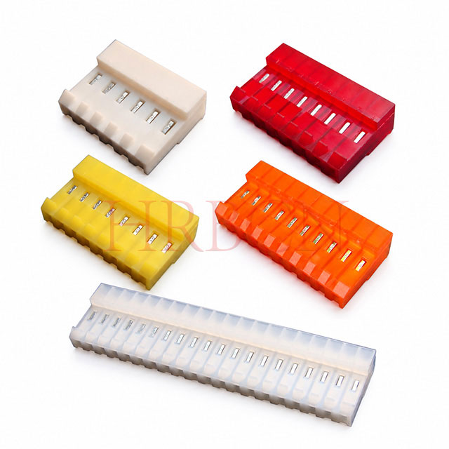
Review HRB’s 2.54mm pitch IDC connectors alongside the relevant mating drawings.
Equipment with an Existing 3.96mm Interface
A 3.96mm connector is a practical starting point when the equipment already uses a compatible 3.96mm header or harness interface.
For new designs, evaluate the available 3.96mm parts against the wire specification, circuit requirements, and installation space. Do not choose the larger pitch solely on an assumption of greater durability.
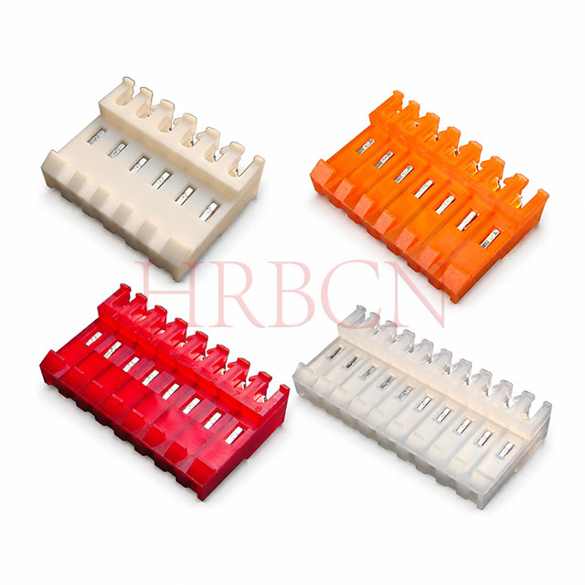
HRB’s 3.96mm pitch IDC connector range provides a starting point for comparing available configurations.
Lighting, Appliances, and Control Equipment
These application categories can involve different wire sizes, electrical loads, and installation conditions. The equipment category alone does not determine the correct pitch.
For example, an appliance control circuit and another circuit within the same appliance may require different connector specifications.
Treat the application name as background information. Base the final selection on the circuit and assembly requirements.
Automotive, Outdoor, or High-Vibration Equipment
Neither pitch by itself proves suitability for these conditions.
Where an application involves vibration, moisture, elevated temperatures, or industry-specific qualification, request supporting documentation for the exact connector assembly.
A locking ramp does not establish a vibration rating, and a dust cover should not be treated as evidence of waterproof protection.
How to Choose Between 2.54mm and 3.96mm IDC Connectors
Step 1: Identify the Required Mating Interface
For replacement projects, record the existing connector and header part numbers. Check the drawings before considering an alternative.
For new designs, select the connector and mating part together before finalizing the PCB footprint.
Step 2: Provide the Complete Wire Specification
Include conductor size, solid or stranded construction, insulation material, and insulation outside diameter.
If ribbon cable is required, provide its conductor spacing and construction. Do not assume that a discrete-wire IDC connector accepts ribbon cable.
Step 3: Define Electrical and Environmental Conditions
Provide the operating current, voltage, ambient temperature, and relevant installation conditions.
Ask the supplier which ratings and test information apply to the proposed part combination.
Step 4: Check the Installation Envelope
Review the complete mated assembly, rather than the connector body alone.
Include the PCB header, wire exit direction, cable bend, assembly access, and space needed to release any locking feature.
Step 5: Confirm Assembly and Purchasing Details
Before placing a production order, confirm:
Connector and mating part numbers.
Circuit count and wire variant.
Required termination tool or fixture.
Assembly and inspection instructions.
Quantity and packaging requirements.
Price and availability for the exact configuration.
Compare quotations on the same basis. Pitch alone is not a reliable guide to purchase cost.
Assembly Checks for Both Connector Sizes
Both pitches require a controlled termination process.
Verify the wire position, circuit order, tool compatibility, and specified seating depth. Inspect for housing damage and confirm that any covers or retention features are correctly installed.
Do not assume that one tool works with both connector families. Also distinguish between disconnecting the mating interface and removing a wire from its IDC contact. Retermination should follow the manufacturer’s instructions.
Frequently Asked Questions
1. Can I replace a 2.54mm IDC connector with a 3.96mm version?
Not as a direct replacement. The contact spacing and mating interface differ. A change may require a different header, PCB footprint, harness, and installation layout.
2. Does a 3.96mm IDC connector always carry more current?
No. Compare the ratings of the exact connector, mating header, and wire combination. Pitch alone does not establish current capacity.
3. Are all 2.54mm IDC connectors designed for ribbon cable?
No. IDC connectors include both ribbon-cable and discrete-wire designs. Confirm the approved cable or wire specification for the selected part.
4. Can the same termination tool be used for both pitches?
Only if the tool manufacturer or connector supplier confirms compatibility with the exact parts. Different housings and contacts may require different tooling.
5. Which pitch is cheaper for volume purchasing?
Request quotations for the actual configurations. Circuit count, materials, contact finish, accessories, tooling, and order quantity can all affect the total cost.
Find the Right IDC Connector for Your Assembly
The choice between 2.54mm and 3.96mm IDC connectors should follow your wire, mating interface, electrical requirements, and available installation space.
Contact HRB with your circuit count, wire specification, mating part details, and expected quantity. Request the relevant product drawing and termination requirements to confirm the proposed configuration before ordering.


