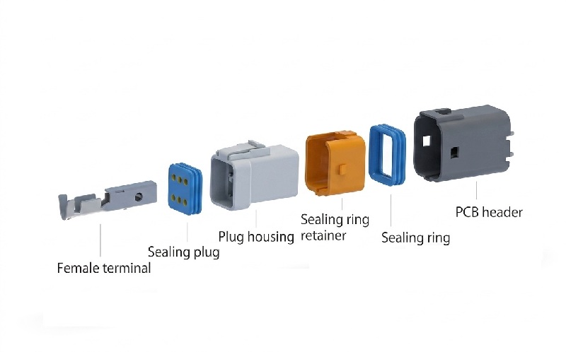
Q: What header orientation does this dual‑row 2.0mm wire‑to‑board waterproof connector adopt?
A: This series features 180° straight vertical PCB header, different from the 90° right‑angle version. It is designed for vertical through‑
hole soldering onto PCB boards.
Q: What wire gauge is compatible with this dual‑row waterproof wire‑to‑board connector?
A: It accepts AWG 22‑24 wires. Please select matched silicone wire seals based on the actual wire outer‑diameter.
Q: Does this dual‑row connector maintain IP67 performance after full mating?
A: Yes. It achieves IP67 rating under IEC 60529 when fully mated and assembled with corresponding wire seals. Not suitable for
continuous deep‑water immersion.
Q: What pin counts are available for M20036‑2XN‑W series?
A: Dual‑row configurations with 3 pins or 4 pins per row are available, namely 2×3‑pin and 2×4‑pin options.
Q: What is the insertion & withdrawal force for this 2.0mm waterproof wire‑to‑board connector?
A: The max per‑pin insertion force is 8 N, and the minimum per‑pin withdrawal force is 0.98 N. Test condition: test with locks disengaged at 5±2 mm/sec speed. Excessive mating force may damage housing or terminals.
Q: How much terminal retention force can the housing provide?
A: The crimped terminal minimum retention force inside housing is 24.5 N. It prevents terminals from backing‑out under vibration, shock and wire‑pull stress. Improper terminal insertion will reduce retention performance.
Q: What is the lock strength of the connector housing?
A: The positive‑lock housing lock strength ≥50 N, tested by axial pulling mated connectors at 1‑5 mm/sec. The robust locking structure ensures stable mating under harsh vibration environments.
Q: What vibration resistance does this 2.0mm waterproof connector offer?
A: The mated connector withstands 10 Hz to 500 Hz vibration sweep, 15 minutes per cycle, 12 cycles in each of three mutually perpendicular directions (36 cycles total, approx. 9 hours). After testing: no appearance damage, contact resistance ≤20 mΩ, and momentary discontinuity ≤1 microsecond.
Q: What mechanical shock level can the connector survive?
A: It survives 50 g, 11 ms half‑sine shock applied in ±X, ±Y, ±Z axes (18 shocks total). Post‑test contact resistance remains ≤20 mΩ with discontinuity ≤1 microsecond, ensuring reliable signal/power transmission under impact conditions.
Q: How does the connector perform under thermal shock?
A: Unmated specimens undergo 48 cycles between ‑40 °C and +130 °C with 30‑min dwell at each extreme. After testing: contact resistance ≤20 mΩ, no dielectric breakdown at 500 V AC, and insulation resistance ≥500 MΩ, suitable for wide‑temperature harsh environments.